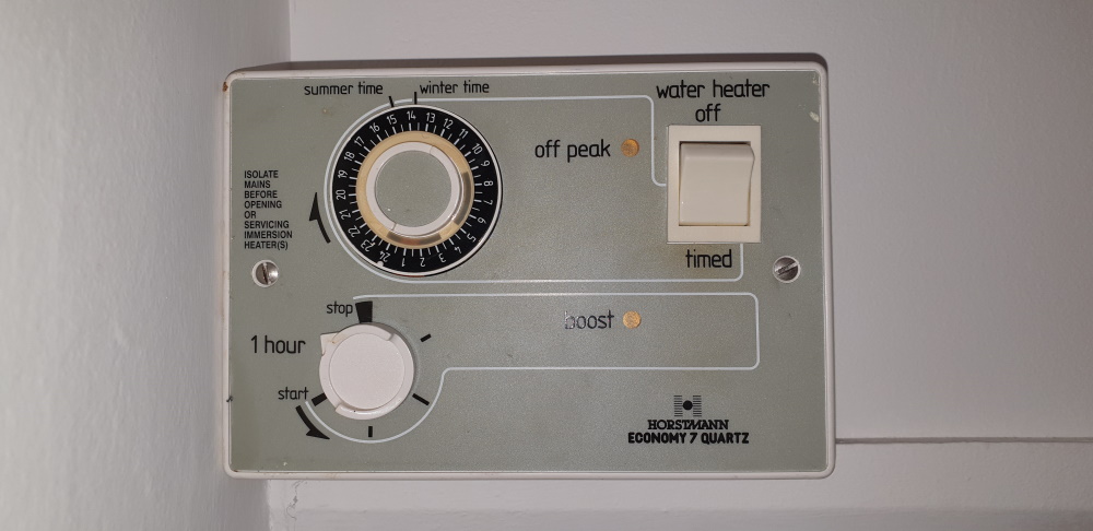
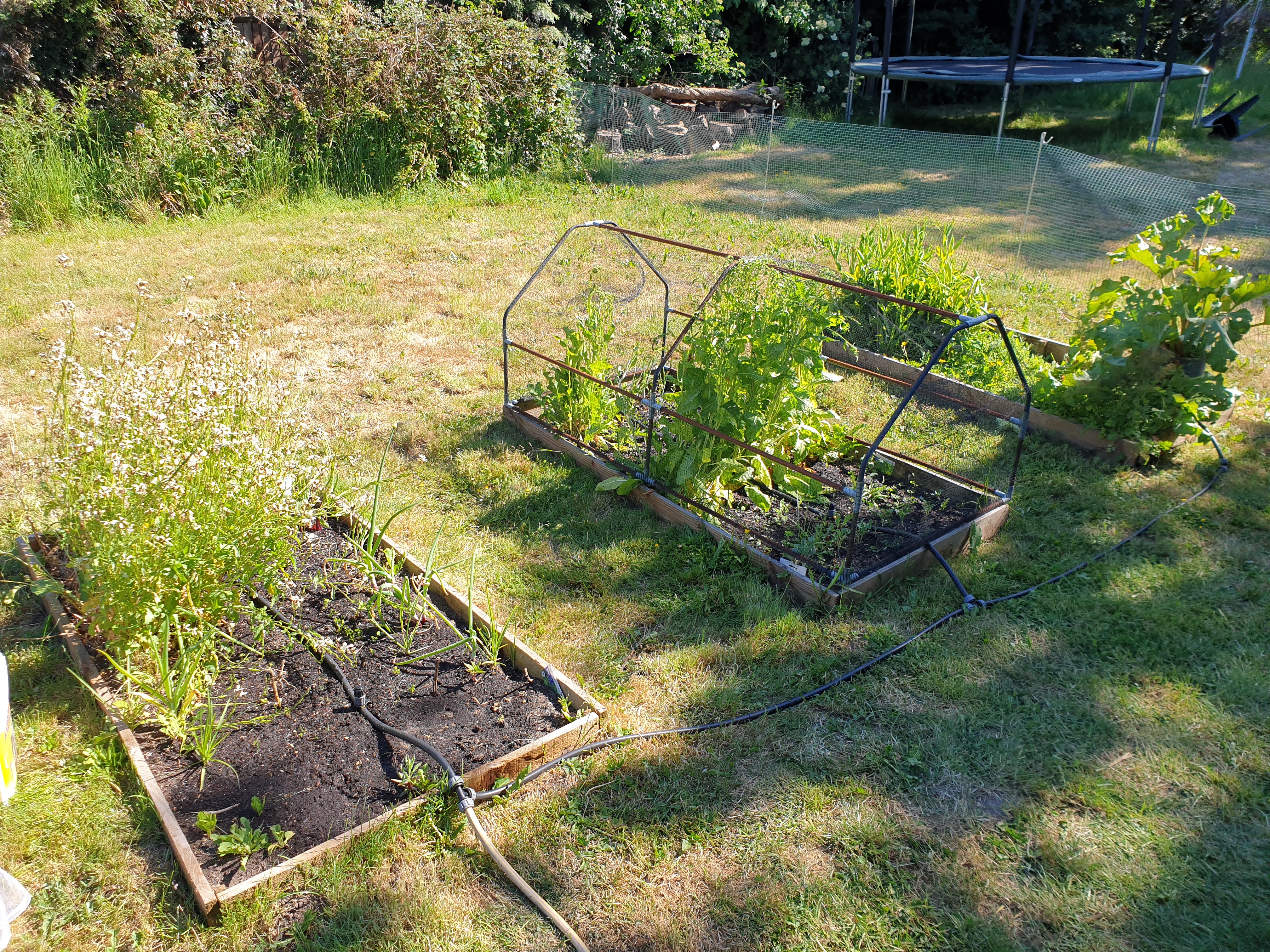
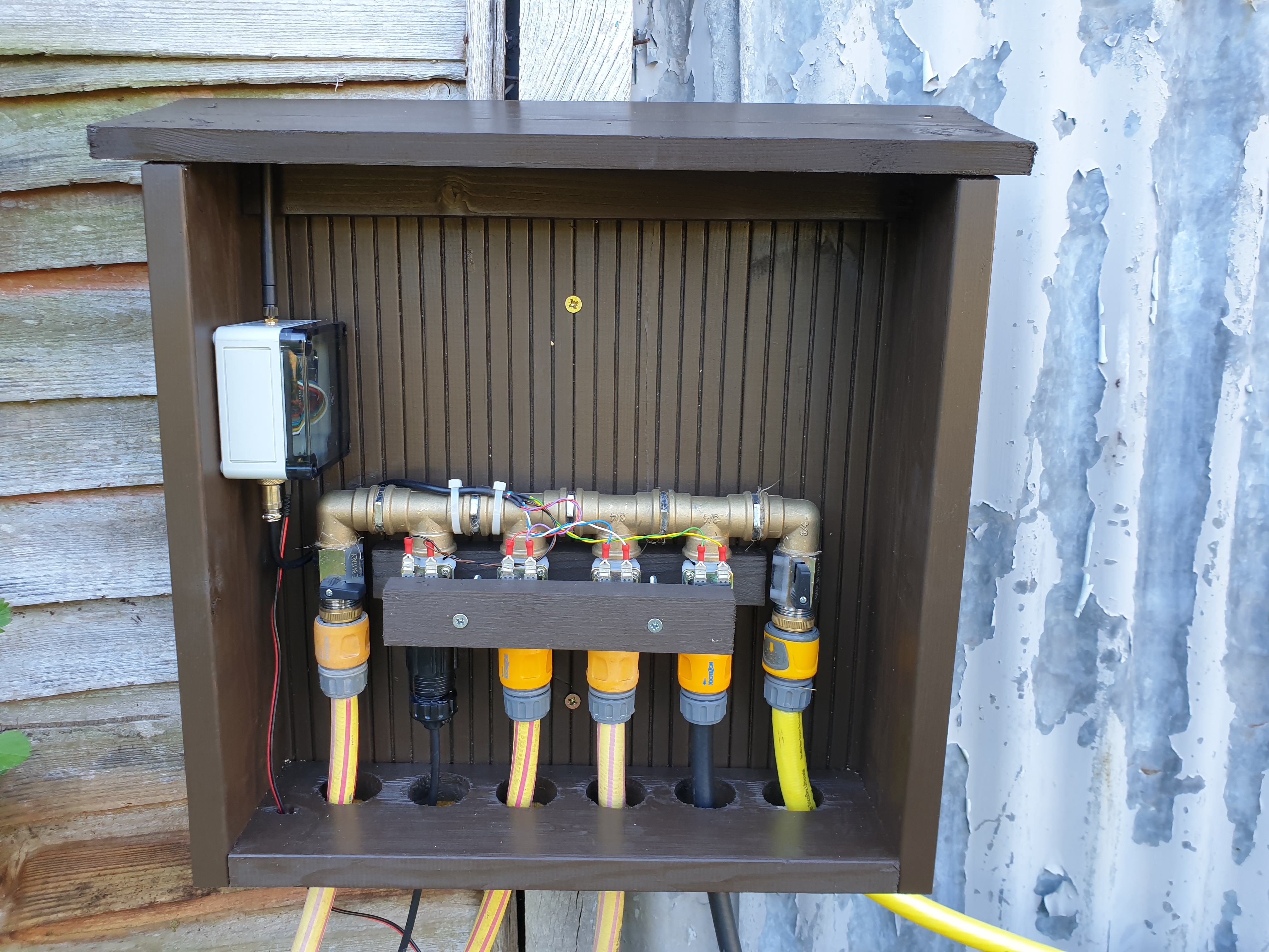
There several things in my house I have been meaning to automate for a while. Some are obvious and simple, like lights and lamps around the house and the water fountain in the garden, others are more complex, like the Economy 7 hot water immersion heater and an automated garden watering system.
After reading a lot of forums and watching a lot of YouTube videos, it was obvious that MQTT was at the heart of any DIY home automation system.
YouTube channels, like Andreas Spiess and SuperHouseTV were a hugely useful resources.
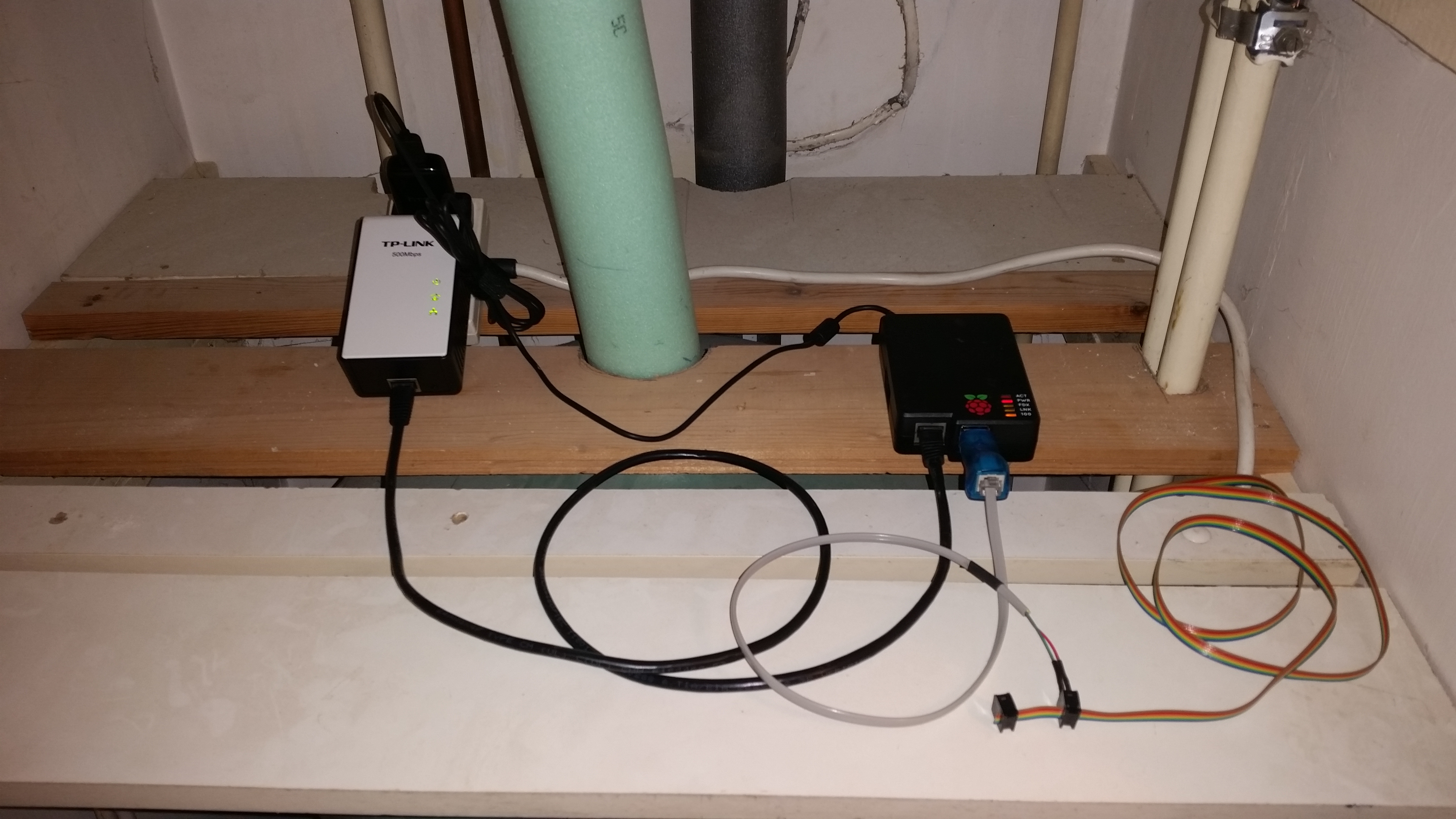
I decided to use a Raspberry Pi running Mosquitto as the MQTT broker and NodeRed for some automation.
There are plenty of tutorials online on how to install these and it’s very simple.
For Mosquitto:
apt-get install mosquitto
apt-get install mosquitto-clients
For NodeRed, the instructions are here.
bash < (curl -sL https://raw.githubusercontent.com/node-red/raspbian-deb-package/master/resources/update-nodejs-and-nodered)
node-red-start
MQTT has a simple “Publish & Subscribe” model (sometimes called “PubSub”). Things can publish messages on a topic which are sent via the broker to anything that has subscribed to that topic. You can subscribe to a particular topic, or to all messages, or filter the topic using wild cards and expressions. It’s very flexible and there is a huge ecosystem of devices that support MQTT.
I setup a simple local software test on the Raspberry Pi to check everything was working after I rebooted. By installing the mosquito clients on the Raspberry Pi I can publish and subscribe using command line tools.
I opened two separate SSH windows, in the first I subscribed to a test topic called “test/message”
mosquitto_sub -t "test/message"
This command will stay running and output any messages that have the topic name “test/message”
In another windows I published a message on that topic with the payload value “hello”
mosquitto_pub -t "test/message" -m "hello"
in the first subscription windows I see the message “hello” appear. It’s all working!
pi@localhost:~ $ mosquitto_sub -t "test/message"
hello
After watching a lot of Andreas and SuperHouse on YouTube, it was clear that the simplest way to automated devices in the home using MQTT was with a Sonoff device, and to reflash this device with an open source firmware called Tasmota.
The Sonoff devices do come with a firmware that provides some simple automation and remote control, but it is not open source. Who knows what data it is collecting. It also needs a public internet connection, whereas a local MQTT Server and Tasmota means all my devices stay on the local network and do not need an internet connection to function.
Sonoff devices are inexpensive, well made and easy to hack; plug sockets, switches and other devices that are all based on the ESP8266 chip. Using these devices Theo Arends and others built an open source MQTT based firmware for Sonoff devices called Tasmota.
Tasmota Code is here on GitHub.
Tasmota Documentation is here.
Tasmota
Tasmota has pretty much everything you need already built in to it, in a very small binary. It includes MQTT support and HTTP management interfaces. Over the air updating means you can reflash the device with new firmware releases using the HTTP interface, rather than having to connect a serial cable. It also has support for dozens of common sensors, like 1-wire temperature sensors, RGB LEDs, etc, all supported out of the box in the code.
Almost all the Sonoff devices can be reflashed to run Tasmota, plus a long list of other hardware, including other ESP8266 based devices and development boards. A full list of supported hardware and sensors is on the Tasmota Template Repository.
I bought some Sonoff S20 sockets. These are mains plug/socket combos than allow you to plug in pretty much any mains powered device into a domestic mains plug and have control over it using home automation. The sockets can switch 10A (about 2kW in the UK) and they have a manual override switch so you can manually turn the device on and off at any time as well.
The initial flashing process is very simple, but you need to take the cover off the Sonoff device, and these are mains voltage when they are plugged in. So do this at your own risk, and watch some YouTube examples first. They do not need to be, and should not be, plugged in to the mains while you flash them. Only plug them in after you have disconnected your programming cable and replaced the covers.
What this video from SuperHouseTV which gives detailed instructions.
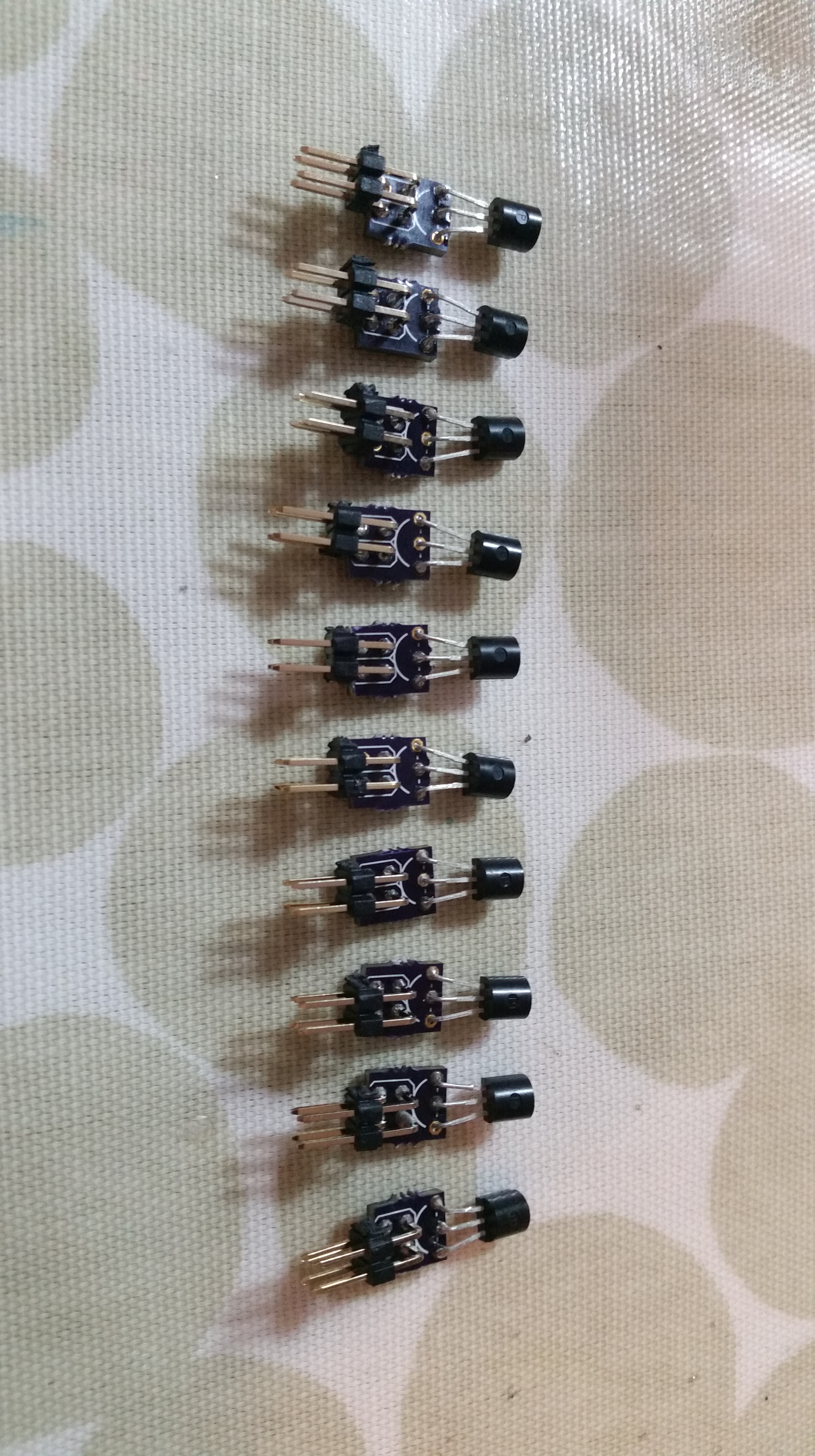
I made simple programming lead from a USB to Serial dongle to program the boards and I didn’t solder headers in to the Sonoff device, I just pushed the pins from the lead in to the PCB hole while it programmed and held them there manually. It takes less that a minute to upload the new Tasmota firmware and once it’s running you can do everything else through the web interface, so you should never need to open the device again.
You need to install the esptool.py on your laptop / computer, which is used to transfer the firmware binary file to the ESP8266 over a serial cable. Once you have identified the com port your serial cable is attached to, the command line is simple.
Download the latest Tasmota firmware from GitHub if you scroll down in that page you’ll find a long list of binary files to download. There are lots of binary files to choose from, but don’t let this confuse you. I have yet to need anything other than the basic binary. It supports all the common functionality you need, and if you need something specific later, you can change the binary over the air.
Just download tasmota.bin from the release page, and copy it to your local directory. I like to add the version number of the release in the filename, so I know which file is which version next time I need to flash something. In this example I named tasmota.bin to tasmota-8.3.1.bin.
Then run esptool.py to upload the binary file to the ESP2866 chip on the Sonoff device.
cd Projects\Sonoff\Tasmota
esptool.py -p COM11 write_flash --flash_size 1MB --flash_mode dout 0x00 tasmota-8.3.1.bin
You will need to substitute the correct COM port for your serial cable and the correct filename for your tasmota.bin.
While flashing via the serial cable, you should see something like this:
esptool.py v2.6
Serial port COM11
Connecting....
Detecting chip type... ESP8266
Chip is ESP8266EX
Features: WiFi
MAC: DE:AD:BE:EF:12:34
Uploading stub...
Running stub...
Stub running...
Configuring flash size...
Compressed 519920 bytes to 355646...
Wrote 519920 bytes (355646 compressed) at 0x00000000 in 31.7 seconds (effective 131.2 kbit/s)...
Hash of data verified.
Leaving...
Hard resetting via RTS pin...
Once the Sonoff device is flashed with Tasmota, you can reboot it, and you should find a new WiFi SSID called “tasmota_xxxx” where “xxxx” is the last part of the devices MAC address.
- Connect to this access point “tasmota_xxxx” on your phone or laptop.
- Browse to 192.168.4.1 on your phone or laptop and you should get the default Tasmota configuration screen.
- Add the WiFi SSID & Password for your house network, click save and reboot.
- Once it has rebooted, it will connect to the house WiFi network and you should be able to find the DHCP IP address in your DHCP server.
- Once you know the local IP you can reconnect to your house WiFi on your laptop and connect directly to the Tasmota device in a browser using its IP number.
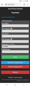
Screenshot of the configuration screen in Tasmota where you enter your WiFi details
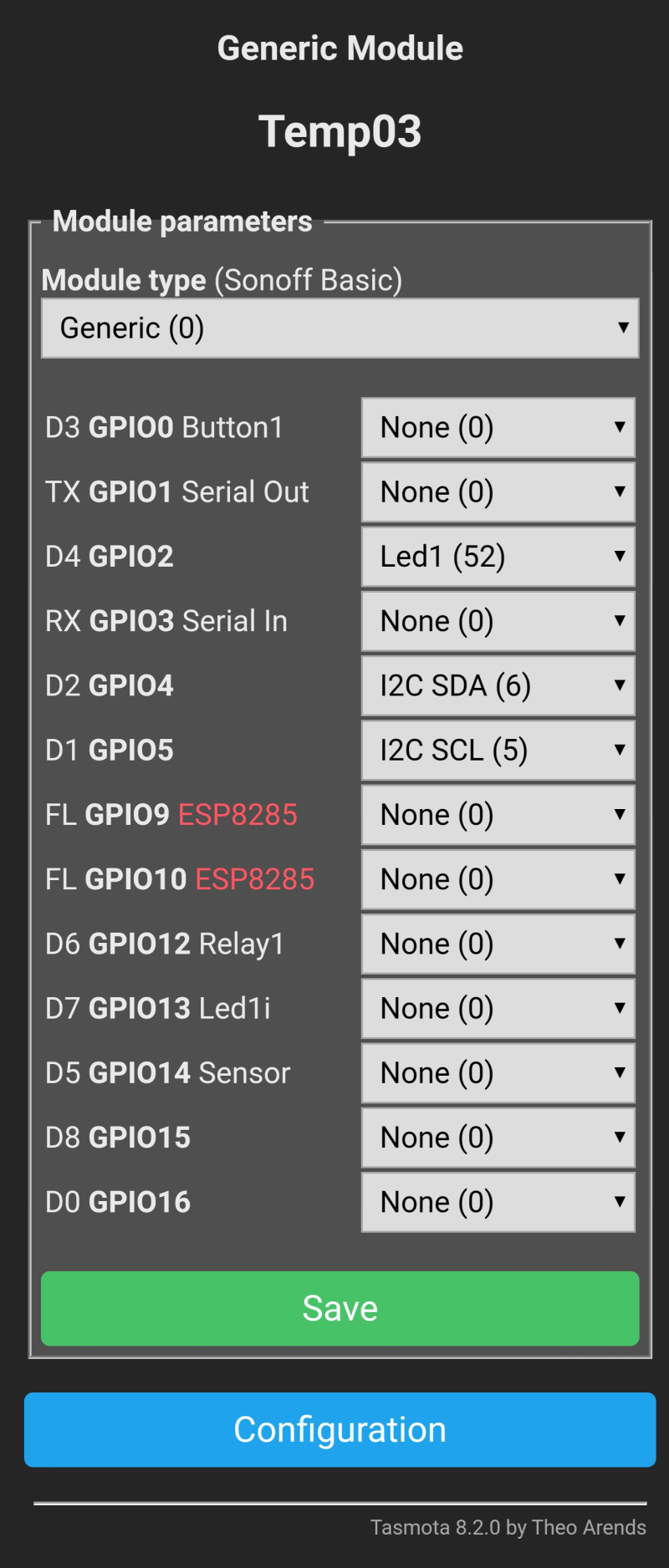
You need to configure a few things in Tasmota to enable MQTT. You need to set the MQTT broker IP address and tell Tasmota what the hardware device is so it know which GPIO pins control which functions.
You can configure this in the web interface. Browse to your device IP number and from the menu select “Configuration” | “Configure MQTT”. Set the “MQTT Host ” to the IP number of your Raspberry Pi Mosquito MQTT Broker you installed earlier.
If you are using a Sonoff S20 plug, from the menu select “Configuration” | “Configure Module” | Module Type = “Sonoff S2X”
Save and reboot and that’s pretty much it. The Tasmota device is fully configured and ready to receive MQTT Messages.
Once you are familiar with the web user interface, it is sometimes quicker to configure your devices via the console. There is a full list of Tasmota commands here.
Once you have flashed your device, do not disconnect the USB cable. Open a serial terminal window with 115200 baud (8N1) and you will have access to the command console.
You can enter you local WiFi credentials using the following syntax :
backlog ssid1 YOUR_WIFI_NAME; Password1 YOUR_WIFI_PASSWORD;
Your device will reboot.
The given IP address will be visible in the serial console output:
00:00:00 Project tasmota Tasmota Version 8.3.1(tasmota)-2_7_1
00:00:00 WIF: Connecting to AP1 HouseWiFi Channel 6 BSSId DE:AD:BE:EF:12:34 in mode 11N as tasmota_3B7DE8-7656...
00:00:03 WIF: Connected
00:00:03 HTP: Web server active on tasmota_3B7DE8-7656 with IP address 10.1.0.73
16:30:48 RSL: tele/tasmota_3B7DE8/INFO1 = {"Module":"Sonoff Basic","Version":"8.3.1(tasmota)","FallbackTopic":"cmnd/DVES_3B7DE8_fb/","GroupTopic":"cmnd/tasmotas/"}
16:30:48 RSL: tele/tasmota_3B7DE8/INFO2 = {"WebServerMode":"Admin","Hostname":"tasmota_3B7DE8-7656","IPAddress":"10.1.0.73"}
16:30:48 RSL: tele/tasmota_3B7DE8/INFO3 = {"RestartReason":"External System"}
16:30:48 RSL: stat/tasmota_3B7DE8/RESULT = {"POWER":"OFF"}
16:30:48 RSL: stat/tasmota_3B7DE8/POWER = OFF
16:30:52 RSL: tele/tasmota_3B7DE8/STATE = {"Time":"2020-06-30T16:30:52","Uptime":"0T00:00:11","UptimeSec":11,"Heap":29,"SleepMode":"Dynamic","Sleep":50,"LoadAvg":19,"MqttCount":0,"POWER":"OFF","Wifi":{"AP":1,"SSId":"HouseWiFi ","BSSId":"DE:AD:BE:EF:12:34","Channel":6,"RSSI":100,"Signal":-39,"LinkCount":1,"Downtime":"0T00:00:05"}}
Yon can either setup the device with extra commands over the serial cable, or do the same in the web console :
backlog MqttHost 10.1.0.90; NTPserver 10.1.0.110; Timezone 0; TimeDST 0,0,3,1,1,0; TimeSTD 0,0,10,1,2,0;
backlog SetOption56 1; SetOption57 1; GroupTopic alldevices;
etc.
Most commands need a reboot, but using the console is so much quicker that clicking through the web interface.
Testing
I tested mine with a simple lamp plugged in to the socket and the socket plugged in to the mains.
By default all Tasmota devices have a “Fallback” topic. This is an MQTT topic which is unique to that device. You do not need to manually configure it (it is derived from the device mac address) and it is listed in the information page on the device.
MQTT Fallback Topic cmnd/DVES_3DDEE5_fb/
The Tasmota / Sonoff device is automatically subscribed to this topic. So, if you send an MQTT Message to this topic from anywhere, it will control the device.
From the Raspberry Pi terminal enter this command using your fallback topic details.
mosquitto_pub -t "cmnd/DVES_XXXXXX_fb/POWER" -m "ON"
then
mosquitto_pub -t "cmnd/DVES_XXXXXX_fb/POWER" -m "OFF"
The lamp will go on and off ! Genius ! 😊
I flashed about a dozen Sonoff S20 plugs and scattered them around the house on various lamps and devices I needed to control. I use them to control lamp in rooms, the lights on my fish tank, the pump in the garden fountain, etc. Nearly everything needs to come on at a particular time in the morning and go off at night.
Automation
I used NodeRed to automate my smart sockets.
Use the fallback topic for the NodeRed topic name in both elements with /POWER at the end. E.g. “cmnd/DVES_3B7DE8_fb/POWER”
Use the payload “ON” or “OFF” to turn the device on or off.
The Inject node can be set to inject at a specific time, or day, or repeat, etc.
I ran this for a few weeks and none of my devices missed a message. They all came on and went off as defined in NodeRed. The Sonoff devices are stable as are Mosquitto and NodeRed.
After a bit more reading, I discovered a custom node call BigTimer, which everyone seems to use instead of the built in “Inject” node. This can be installed through the interface. Just go to “Manage Palette” in NodeRed and search for “bigtimer” which will find “node-red-contrib-bigtimer” and install it.
This combines on and off messages in a single node, making the workspace a lot less cluttered, plus it has all kind of other useful features like “sun rise” and “sun set” which takes your GPS location and works out when it will get dark. Useful for controlling fish tank lights or outside lights.
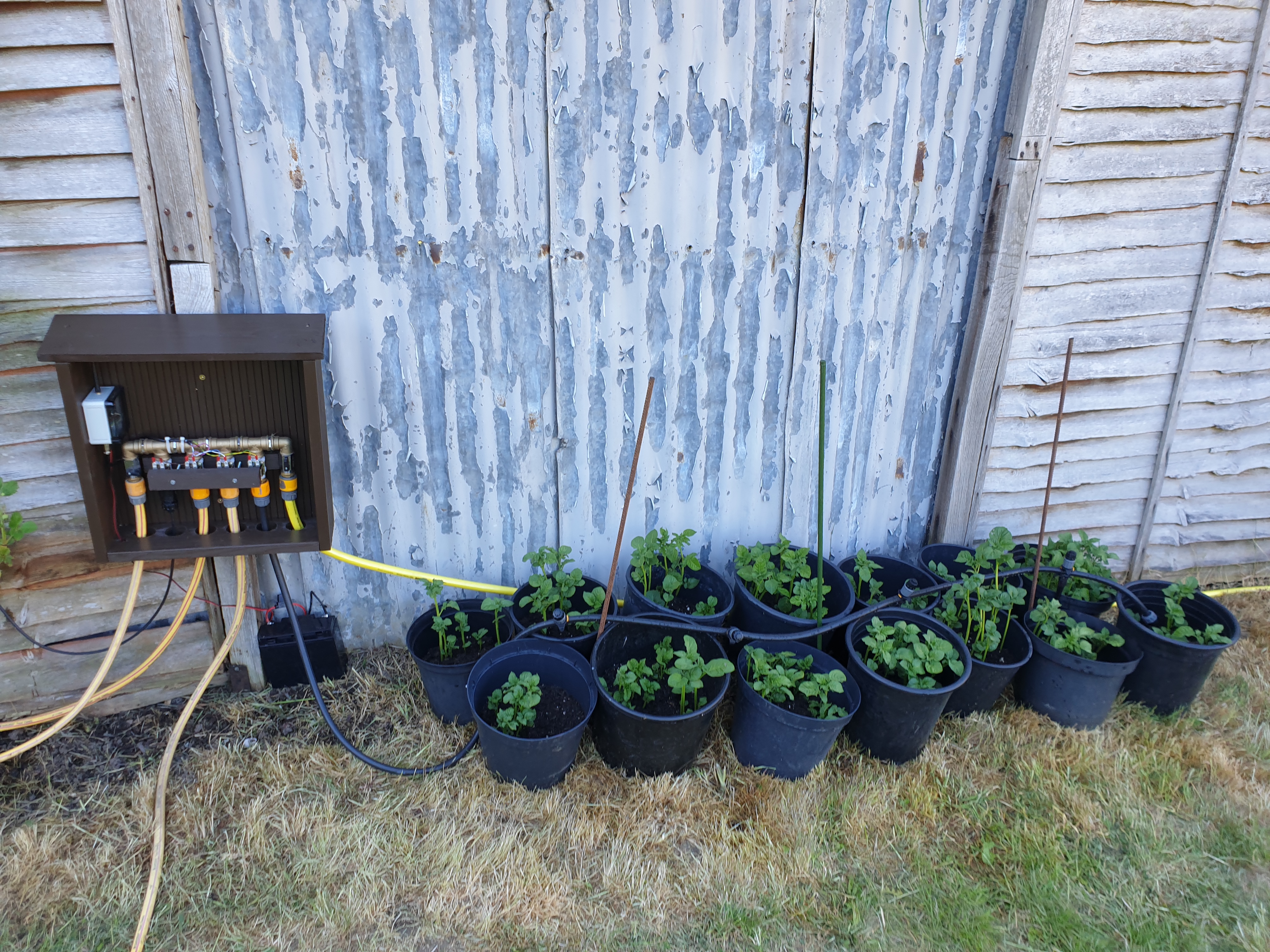
You can also define certain days or months the command will operate in, useful for having your outside watering system only on during the summer months, for example.
I replace all my inject nodes with BigTimer and I have been using that without issue ever since.
My garden fountain is on during the day at sunrise, and automatically goes off at sunset !
The final nice to have is a mobile app that I can use to manually override the automation if required and switch things on and off manually. The easiest way to do this initially is to use the Dashboard feature of NodeRed. The limitation of this is that I can only access it from within my local network as my NodeRed server is not open to the public on my firewall. However this is acceptable for the time being. We can change it later and add more feature. There are plenty of full blown home automation interfaces I can add later, including Google Home automation with voice control.
The Dashboard feature of NodeRed can be installed using the Palette Manager, or following the instructions on the dashboard website.
You can add gauges, buttons, switches, etc. To start with, I added a switch for each socket. You can just add the switch to the flow and connect it to an MQTT topic. This works, but if you manually change the state of the switch outside of NodeRed, by pressing the physical button on the socket for example, the dashboard element wont know about this and update the state.
To fix this you have to subscribe to the “stat” status messages coming from Tasmota on the device and feed them back in to the dashboard switch element. I added a simple function before the dashboard switch element to change the topic from the “stat” topic it receives to a “cmnd” topic the switch needs to change state.
For example, For SocketA I subscribed to “stat/socketa/POWER” in NodeRed and the function after this node changes the topic to “cmnd/socketa/POWER” and feeds it in to the dashboard element. The output of the dashboard element send the message out as MQTT again when the switch is pressed.
msg.topic = "cmnd/socketa/POWER";
return msg;
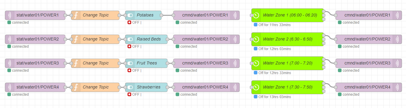
My final NodeRed flow looks like this for all my sockets. I have a dashboard flow for each one, and a BigTimer node for those that I need to automate.

NodeRed flow for control of Sonoff Sockets
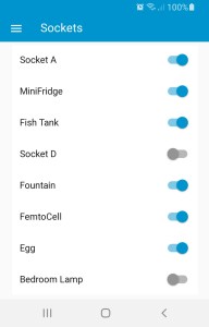
Screenshot of the NodeRed Dashboard interface on my phone.
Home automation phase one complete ! 🙂