When I first started selling my IOT MOSFET shields on Tindie, I honestly didn’t think I’d sell many. I thought I might sell the odd one or two, but instead I’ve sold hundreds, all over the world! Which is quite amazing. Thank you to everyone who bought one, I’m pleased it solved a problem for you.


This of course created its own problems. I needed to create a more streamlined logistics and more automated testing to fulfil orders efficiently. Luckily 95% of the orders are less than five boards, so they all fit in a small A5 padded envelope, and after a little research I found self-adhesive laser printable labels that fit the UK Royal Mail labels exactly, so processing orders is very easy and efficient. I print the packing slip, buy the postage online and print out the address and customs declaration labels. Then insert the packing slip and products in to an envelope, seal it and stink on the labels. It literally takes a few seconds.
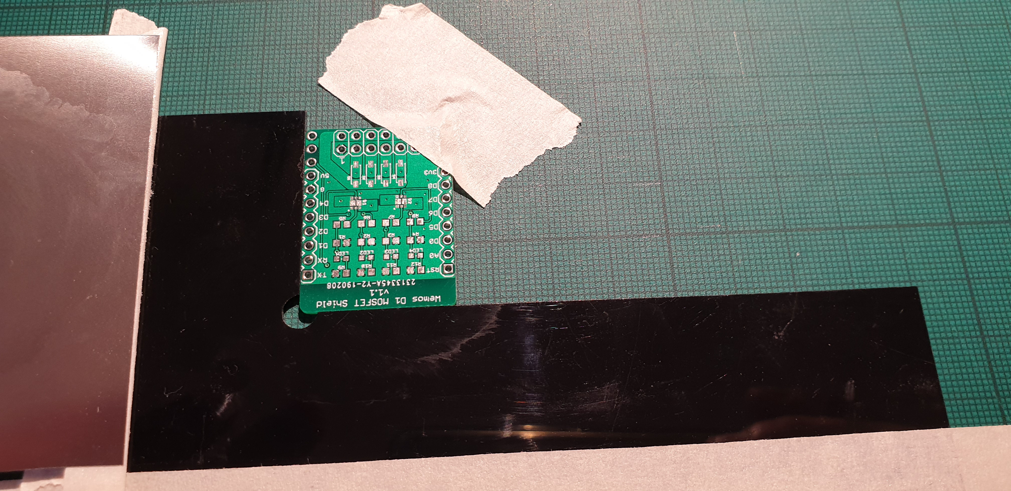
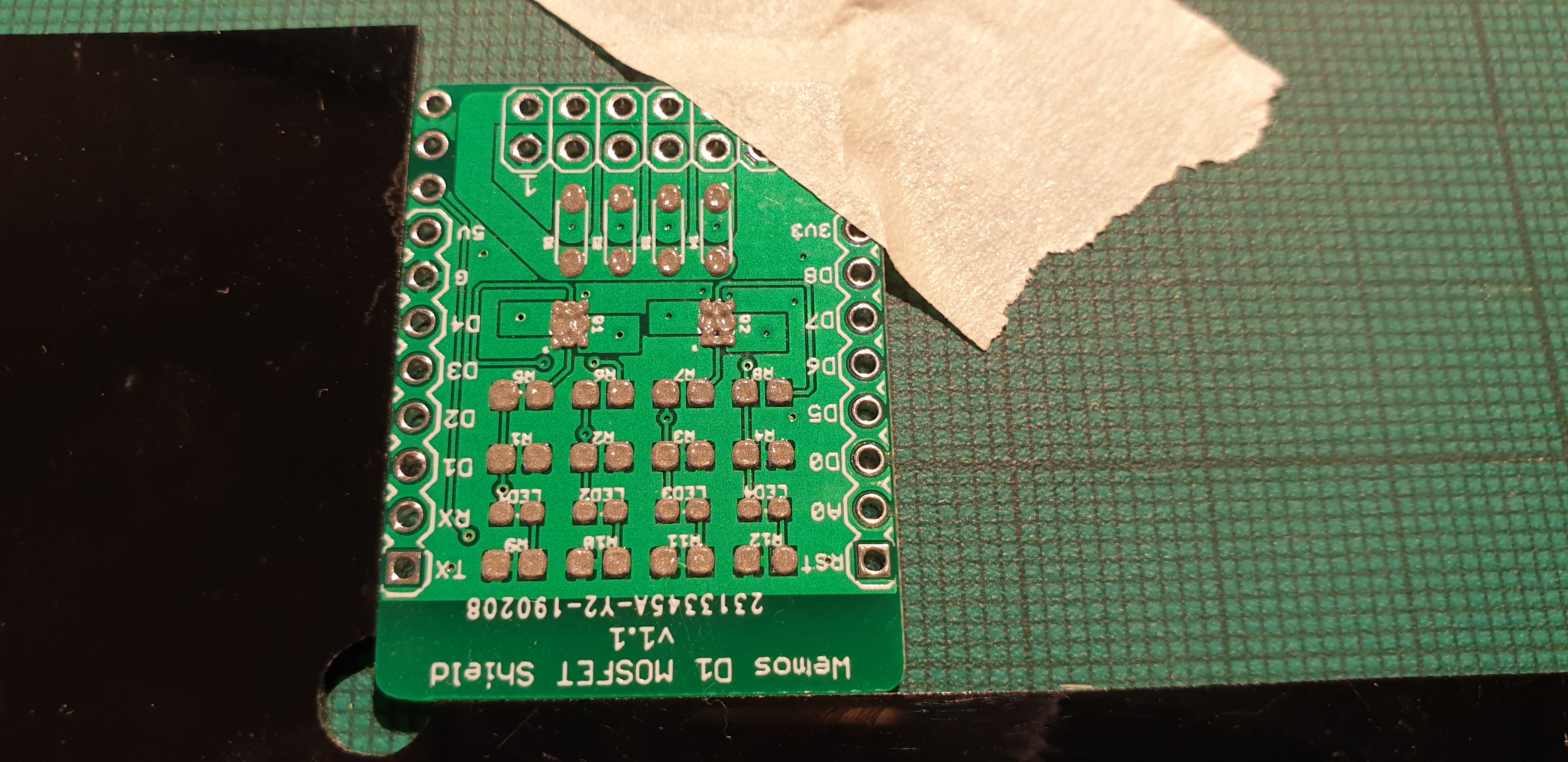
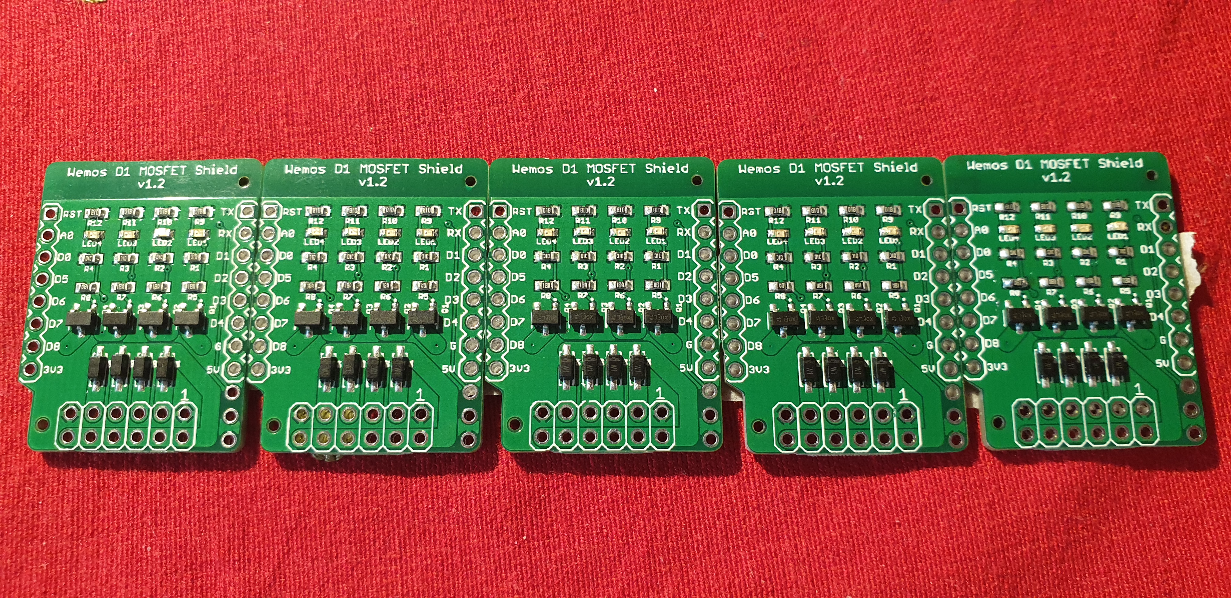
The only complex part is testing the boards. In theory, the boards are tested by the PCB manufacturer before being shipped to me. But they are built on panels. I need to separate them and there is a chance they could be damaged by the separation and handling process. It is also another excuse for an interesting project.
The two features of the boards I need to test are the LED indicators and the MOSFET operation. To test for potentially weak solder joints, I wanted to test at a relatively high current, rather than just continuity.
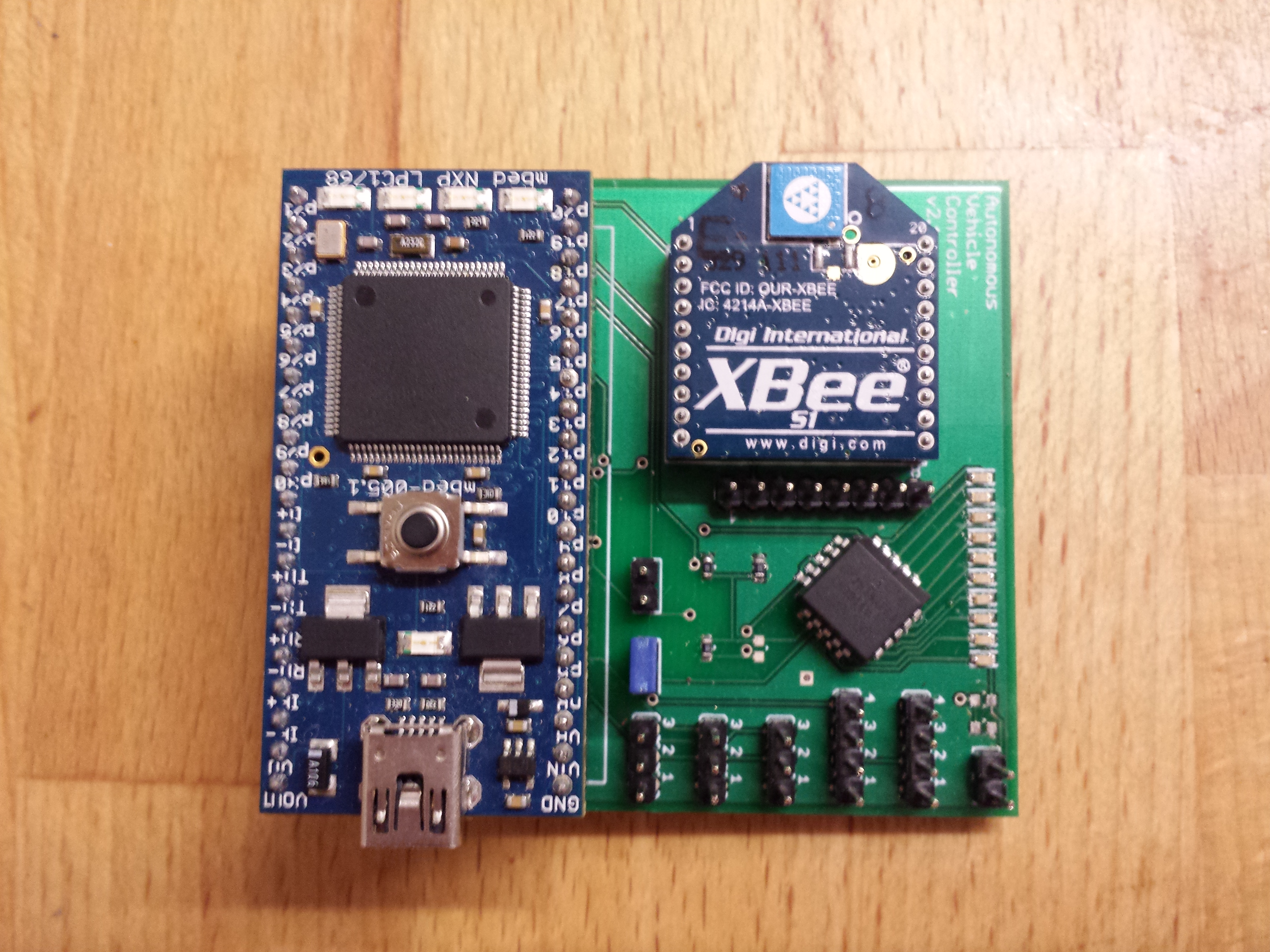
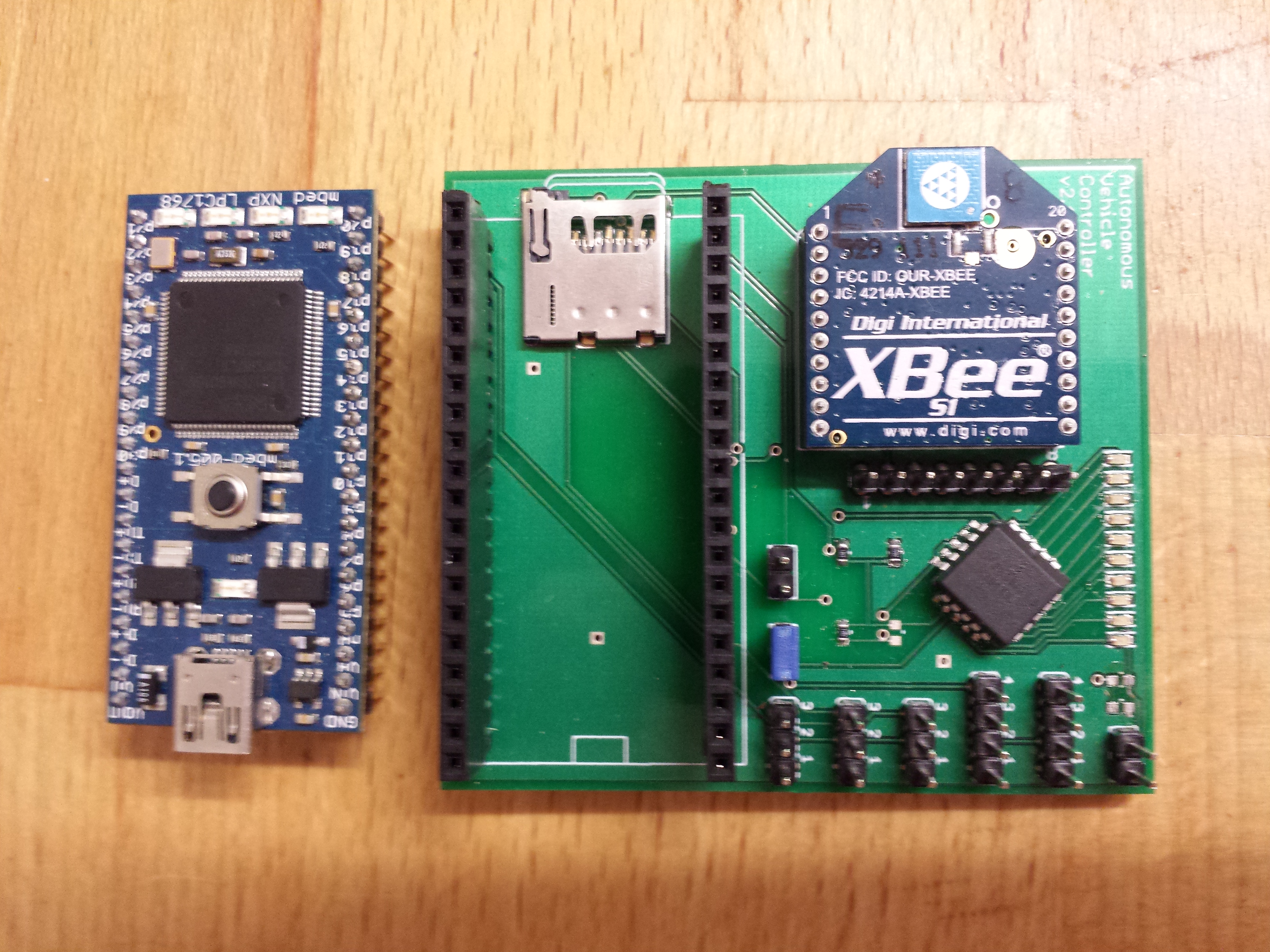
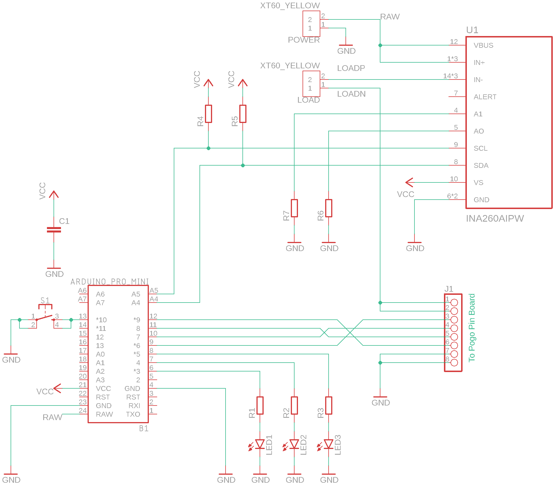
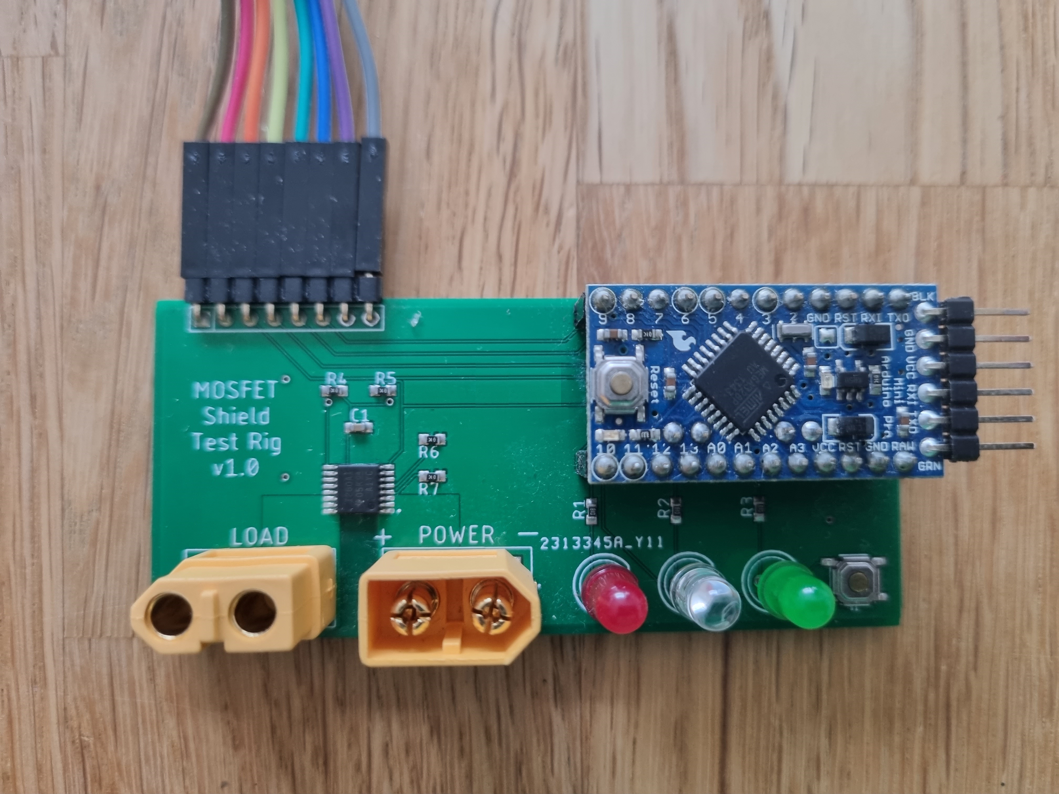
I designed a test that switches each of the MOSFETs on and off sequentially. There is a load connected to the MOSFETs, so I can test at a specific current. I measure the current for each MOSFET under test and check its within range. I use an INA260 Digital Current Monitor IC which can measure currents up to 15A, but during the test I only draw about 2A. However, I can adjust the load to set a higher current. I also added an Arduino microcontroller to execute the test, and a red, amber and green LED to provide feedback. Amber means the test is running, red and green mean pass or fail.
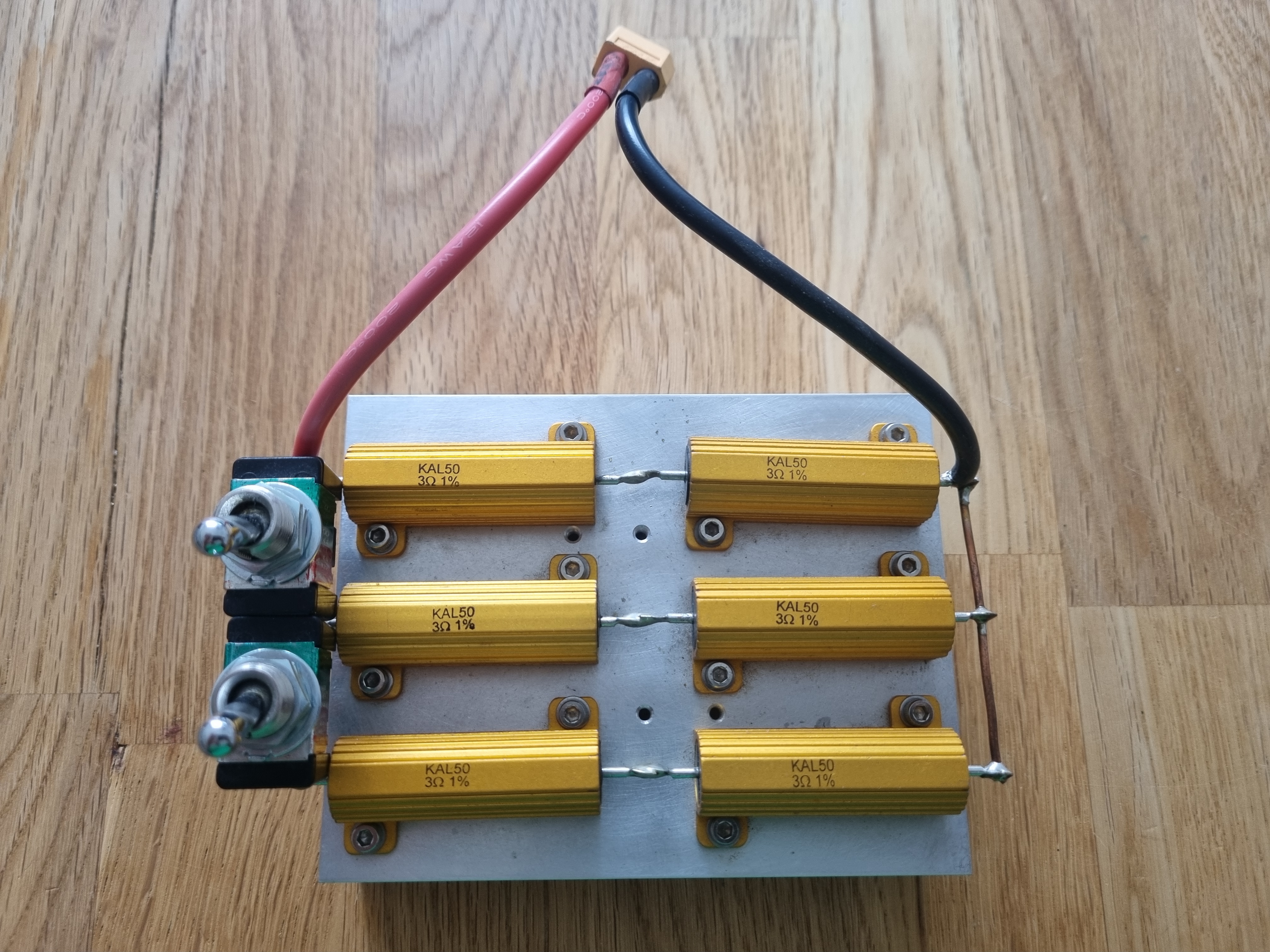
I built the variable load using some high power resistors bolted to a heat sink, which will be useful for other projects too. The resistors are 3 ohms @ 50 watts. I have them arranged in a 2S3P grid, with switches between each of the 3 parallel rows, so I can switch the load to be 6 ohms, 3 ohms or 2 ohms. At 12v this would generate 2A, 4A & 6A respectively, which is perfect for this project, but would also be useful for other projects too. I mounted an XT60 connector, so I could plug it in to other projects if required.
The INA260 uses I2C to communicate with the microcontroller. There an existing library to interface with it, making the software is very easy.
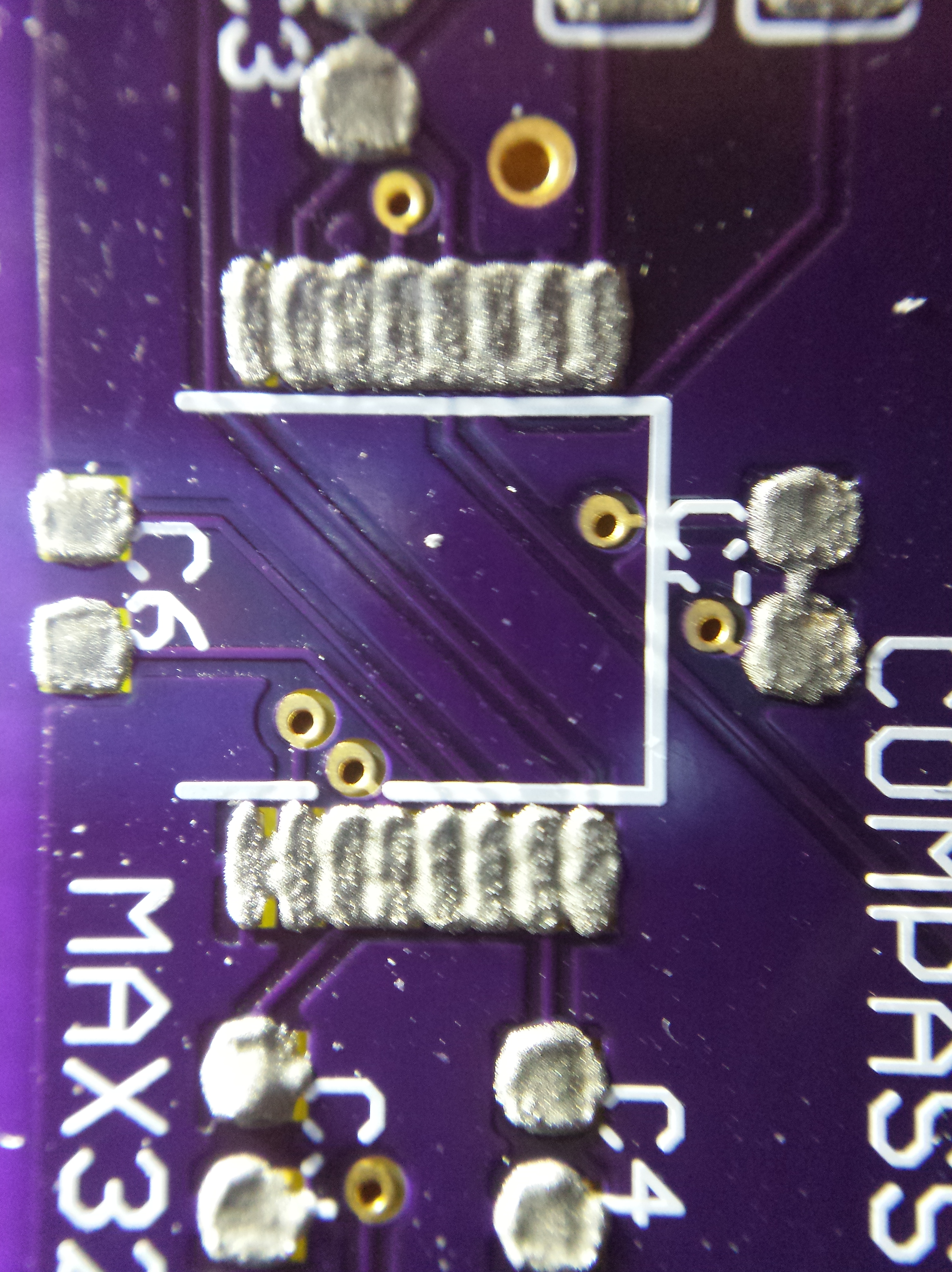
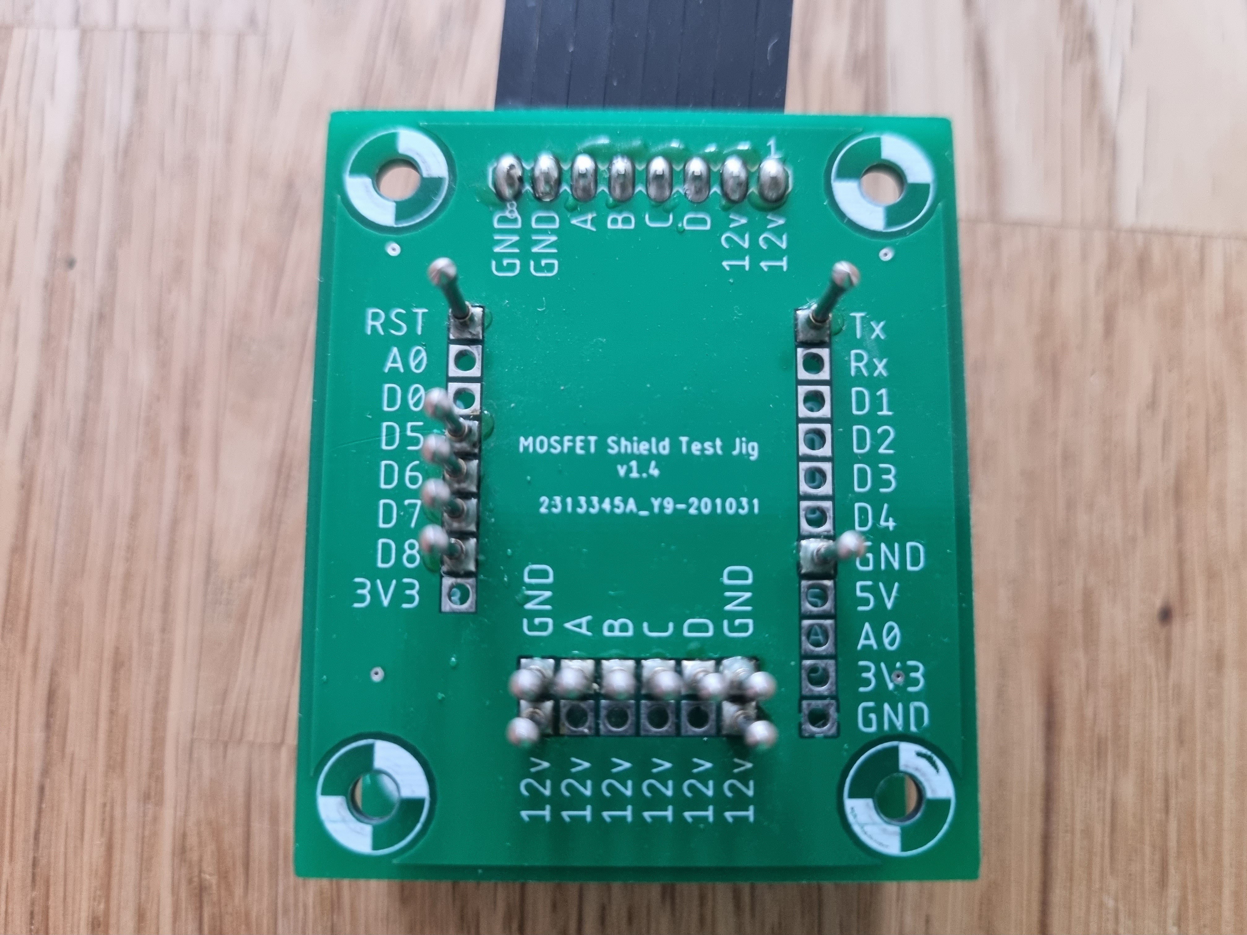
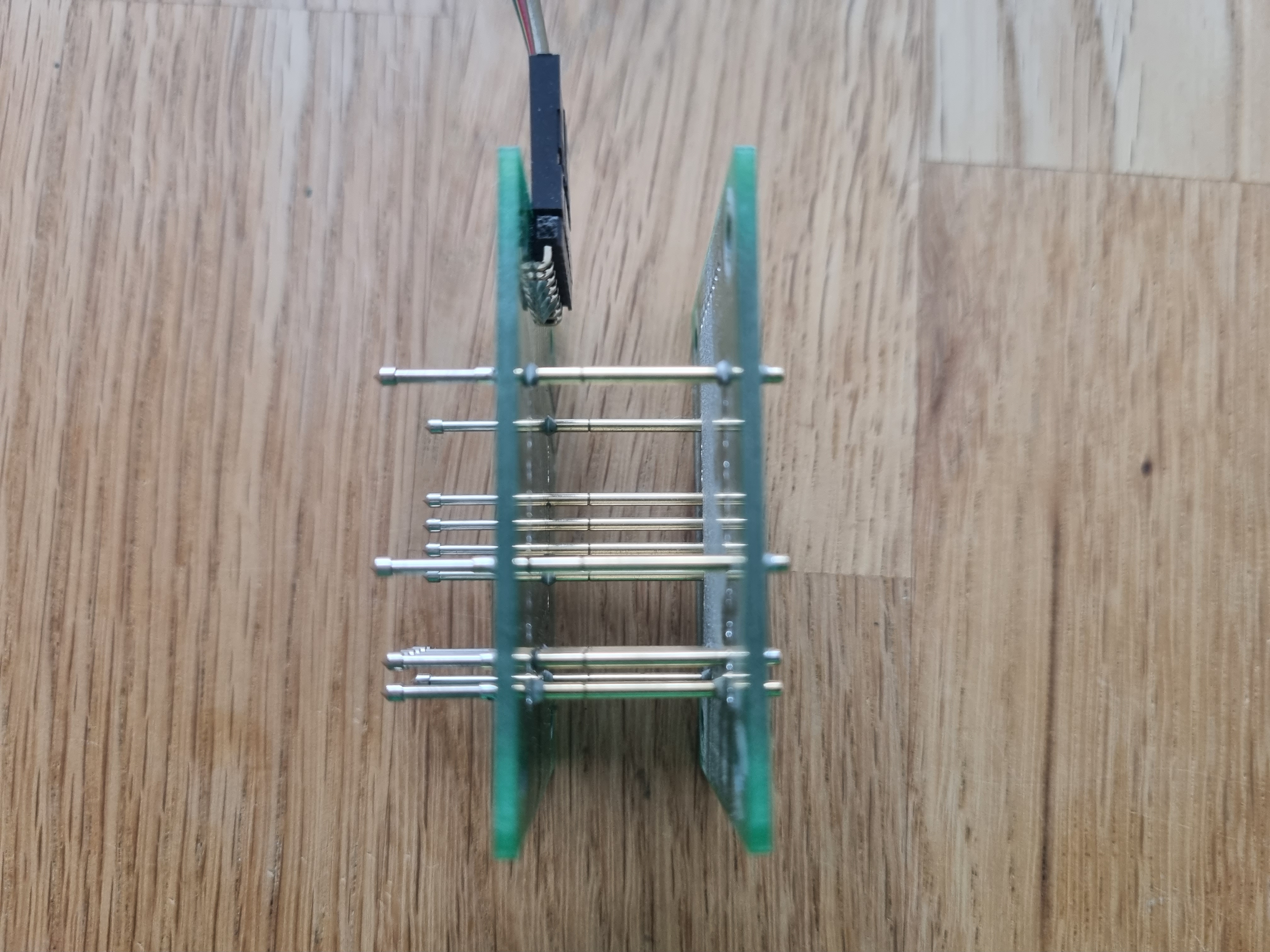
An interesting problem was how to interface to the MOSFET shield under test to allow for quick testing. I had seen a few videos on YouTube using pogo pins and wanted to try them. Pogo pins are tiny spring mounted pins with various shaped heads on them to contact test points of pads on PCBs.
I decided to keep the pogo pin interface board on a separate PCB to the test circuit. This way if I change the MOSFET shield design or design a shield with a different layout I can use the same test jig, with different interface boards.
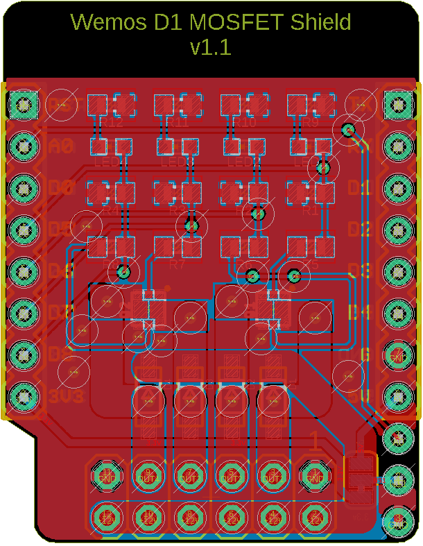
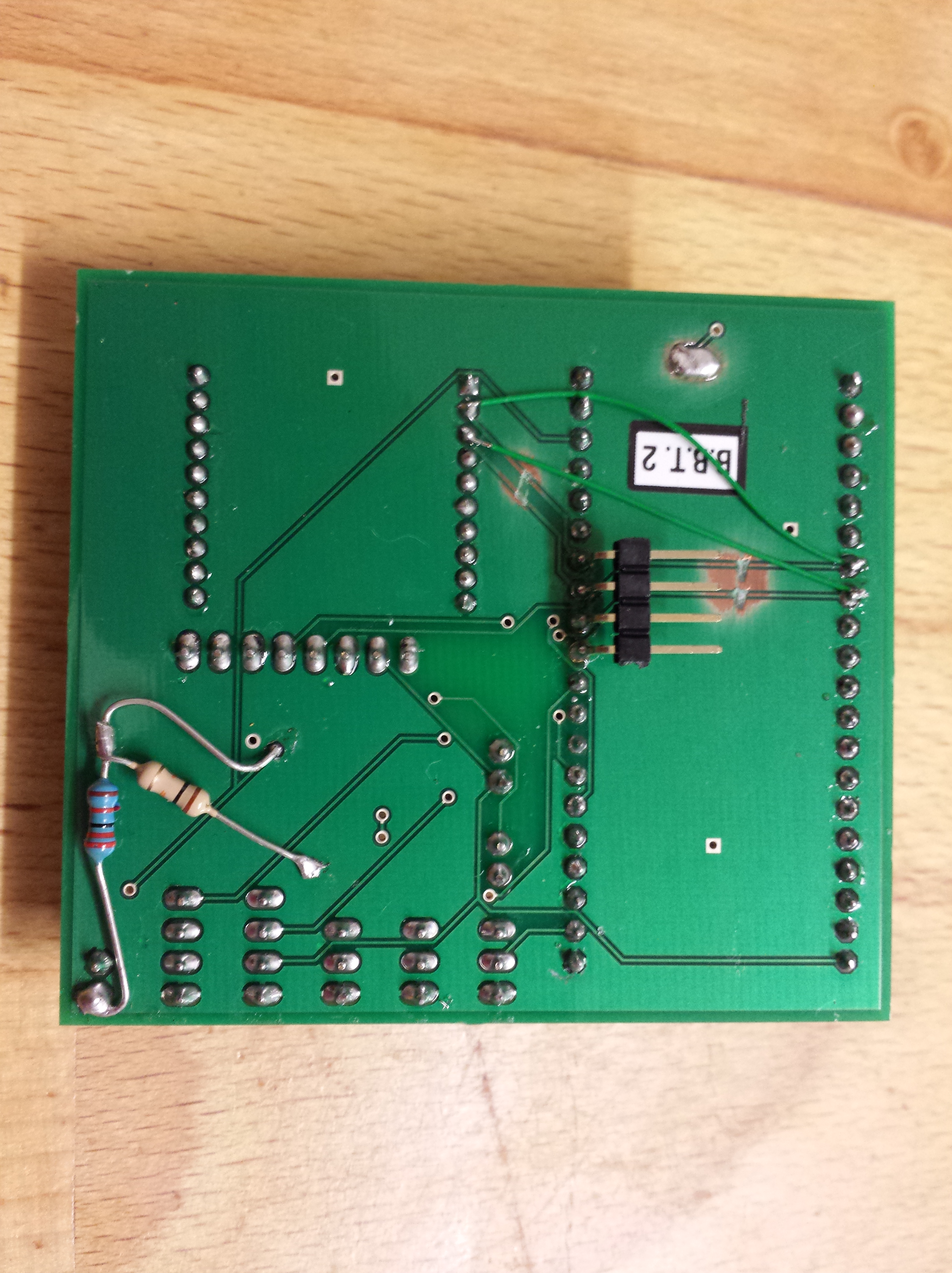
I prototyped the circuit on a breadboard before committing it to a custom PCB.

The software is very simple;
- Measure the voltage with the INA260 to ensure the power is on.
- Turn on the Amber LED to signal the test is underway.
- Turn on each MOSFET in sequence and measures the current flowing through it. If the current does not exceed the acceptable threshold, mark the test as failed.
- Once all MOSFETs are tested, turn off the Amber LED and turn on either the Red or Green LED, depending on if the test has passed or failed.
- Pause for 5 seconds to allow the operator to put a new board on the test jig for testing.
- Rinse and Repeat.
#include <Adafruit_INA260.h>

//A4 (SDA) and A5 (SCL)
#define CH1 6
#define CH2 7
#define CH3 8
#define CH4 9

#define LED_RED 3
#define LED_GREEN 5
#define LED_AMBER 4

#define V_THRESHOLD 6000  //6v
#define I_THRESHOLD  500  //500mA

float nV;
float nI;
int bPassed = true;

Adafruit_INA260 ina260 = Adafruit_INA260();

void setup() {
  pinMode(LED_BUILTIN, OUTPUT);
  pinMode(CH1, OUTPUT);
  pinMode(CH2, OUTPUT);
  pinMode(CH3, OUTPUT);
  pinMode(CH4, OUTPUT);
  pinMode(LED_RED, OUTPUT);
  pinMode(LED_GREEN, OUTPUT);
  pinMode(LED_AMBER, OUTPUT);

  Serial.begin(115200);
  Serial.println("Setup...");
  if (!ina260.begin()) {
    Serial.println("Couldn't find INA260 chip");
    while (1);
  }
  Serial.println("Found INA260 chip...");

}

void loop() {
 runTest();
}

void runTest(){
  digitalWrite(CH1, LOW);         //MOSFET A OFF
  digitalWrite(CH2, LOW);         //MOSFET B OFF
  digitalWrite(CH3, LOW);         //MOSFET C OFF
  digitalWrite(CH4, LOW);         //MOSFET D OFF
  digitalWrite(LED_RED, LOW);     //RED OFF
  digitalWrite(LED_GREEN, LOW);   //GREEN OFF
  digitalWrite(LED_AMBER, LOW);   //AMBER OFF

  Serial.println("Begining Test...");
  delay(1000);
  bPassed = true;

  nV = ina260.readBusVoltage();
  Serial.print("Bus Voltage: ");
  Serial.print(nV/1000);
  Serial.println("V");

  if (nV > V_THRESHOLD) {
    //power is on
    digitalWrite(LED_AMBER, HIGH);   //AMBER ON - Running ...
    Serial.println("Testing...");
    Serial.println("Channel A:");
    testChannel(CH1);
    Serial.println("Channel B:");
    testChannel(CH2);
    Serial.println("Channel C:");
    testChannel(CH3);
    Serial.println("Channel D:");
    testChannel(CH4);
  } else {
    Serial.println("Power Off...");
    bPassed = false;
  }

  if (bPassed){
    digitalWrite(LED_RED, LOW);      //RED OFF
    digitalWrite(LED_GREEN, HIGH);   //GREEN ON - Pass!
    digitalWrite(LED_AMBER, LOW);    //AMBER OFF
    Serial.println("PASSED");
  } else {
    digitalWrite(LED_RED, HIGH);     //RED ON - Fail!
    digitalWrite(LED_GREEN, LOW);    //GREEN OFF
    digitalWrite(LED_AMBER, LOW);    //AMBER OFF
    Serial.println("FAILED");
  }

  Serial.println("All done.");
  delay(5000);  // Wait 5 seconds to load next board to test.
}

void testChannel(int nC){
  digitalWrite(nC, HIGH);
  delay(500);
  nI = ina260.readCurrent();
  Serial.print("Current: ");
  Serial.print(nI);
  Serial.println("mA");
  if (nI > I_THRESHOLD){
    Serial.println("Passed!");
  } else {
    Serial.println("Failed!");
    bPassed = false;
  }
  digitalWrite(nC, LOW);
  delay(500);
}
The test jig worked well, and once you get in to right rhythm of changing boards after the test, it takes about 10 seconds to test each board. You can efficiently test a whole batch within a few minutes.
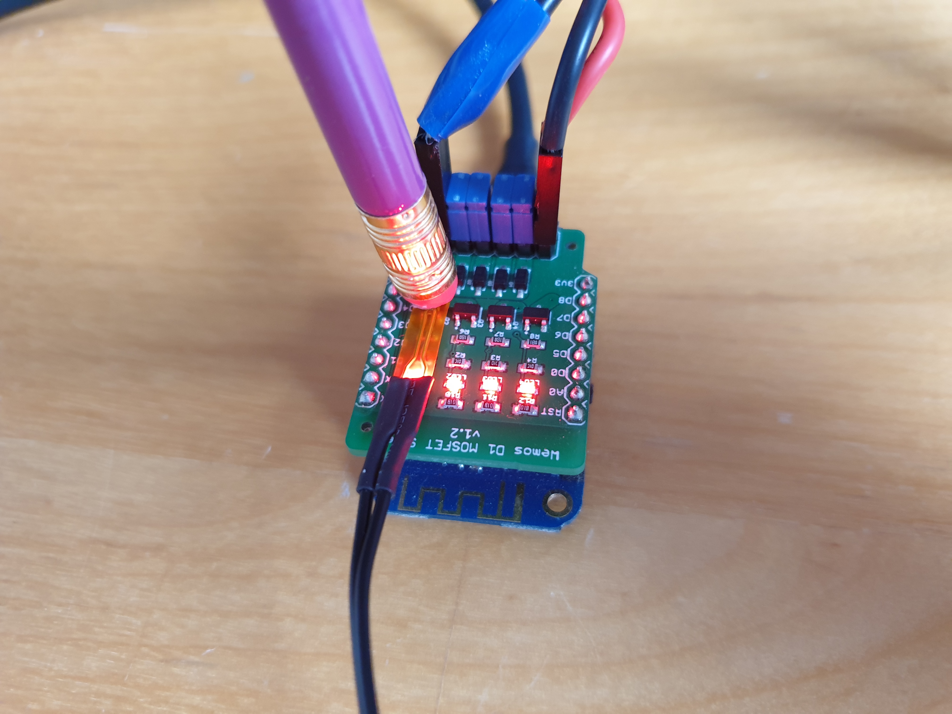
And just to prove the tester really does fail a broken board, I cut the trace to the 3rd MOSFET on a test board and ran a test on it. You can see in the video, the third LED fails to light correctly, and the test jig reports a failure by lighting the red LED at the end of the test.
Having used the jig to test a few hundred boards, there are some improvements I could make for version 2. A 3D printed frame to help align the board on the pogo pins would be useful to help with changing the boards quickly. This could perhaps also include a mechanical switch, which would start the test when the board was pressed down, rather than relying on a timed sequence. In addition I should add a sounder to make a pass and fail noise, so I don’t have to stare at the LEDs. An audio confirmation would make it easier to use. Maybe I’ll make a version 2 at some point, but this version works perfectly and has significantly improved the speed I can test the boards. It also highlights the quality of the manufacturing process, as to this day, I’ve never had a board fail the test.