
The frame of the robot is built from MicroRax but it has no “sides”. I needed to mount some switches, etc. plus I wanted to mount the Arduino board securely and the two mounting holes in the Arduino are at very specific locations which would be better secured to a flat surface. They didn’t line up with the MicroRax.
The initial prototype had a hardboard base, but I thought I’d use the opportunity to learn how to get laser cut plastic. I found a supplier, Ponoko, which had a very simple interface. A lot of laser cutting houses use AutoCAD or Illustrator file formats to define the shape to cut. As I didn’t have an applications that can produce these, I liked Ponoko, as it used PNG. This can be generated huge number of apps, a lot of which are free.
Ponoko provide a sample template. The format is very straight forward. The colour of the line in the file defines the cut the laser will make. E.g. Cut, engrave, etc. They also have a huge array of materials, including acrylic, leather, card, wood, paper, rubber, etc.
I designed a top and a bottom. The bottom has a hole for the cables. The top is engraved (no reason other than I wanted to try it and it looks cool :-)) I didn’t get the holes for the switches laser cut, I drilled them, as I didn’t know at the time what switches I would be using.
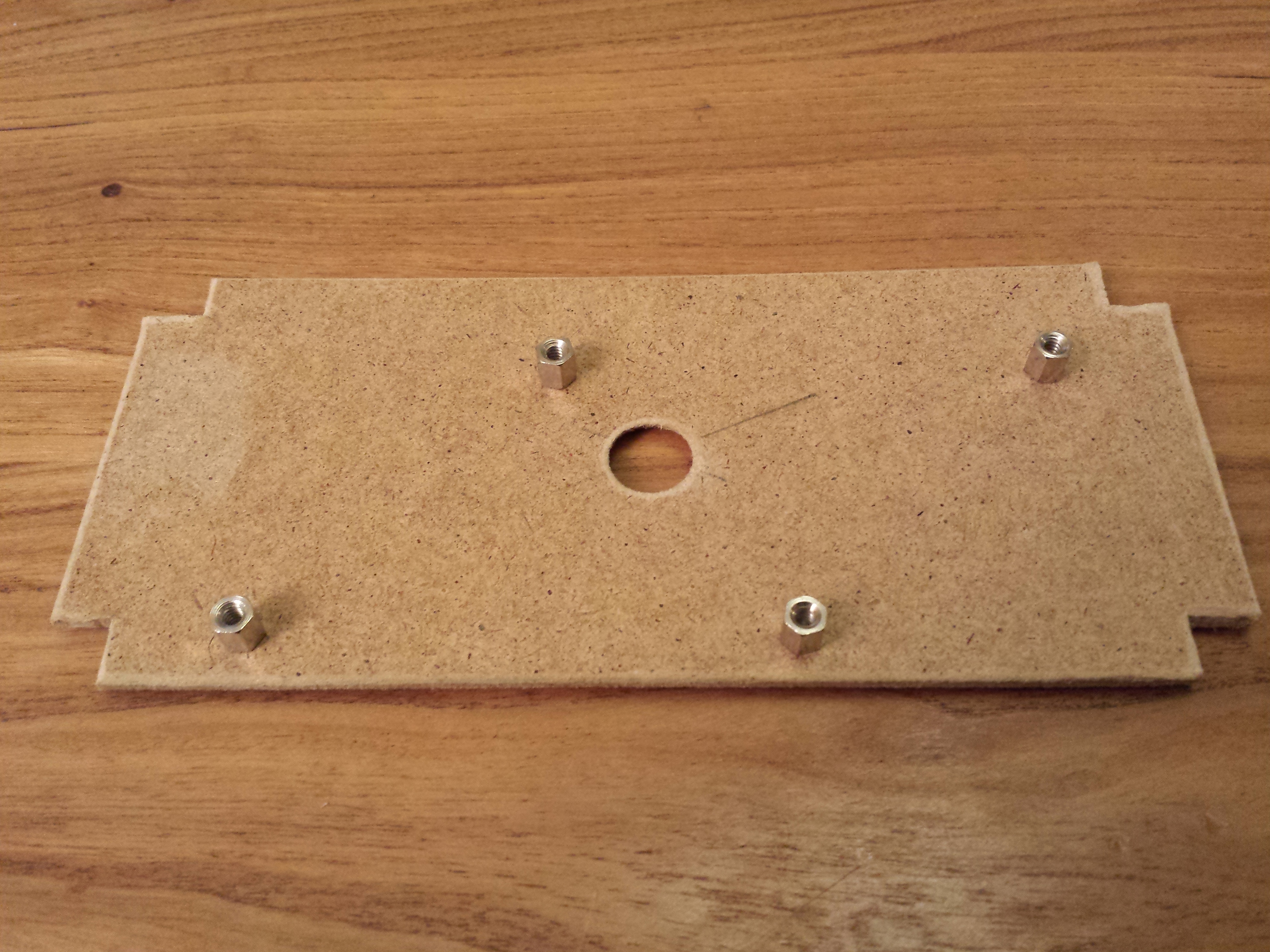
Hardboard BalanceBot floor with Arduino PCB mounts
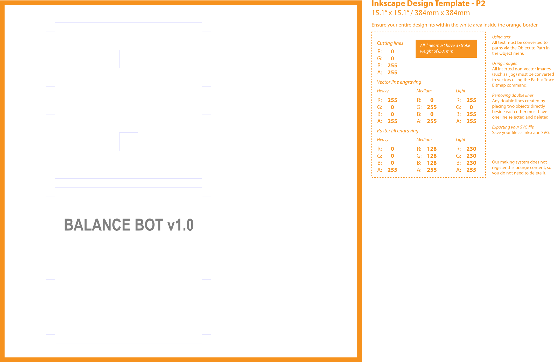
PNG file used to laser cut the acrylic. Different coloured lines represent different types of cut or engraving.

Laser Cut Acryilic sheets. Cut by Ponoko.

Laser cut acryilic top with laser engraving
The acrylic panels made the robot look very professional, in fact people ask me where I bought it 🙂
The panels made mounting the boards and switches trivial. I used self-adhesive PCB supports for the Arduino. The holes on the Arduino are 3.2mm. I found PCB supports 6.4mm high from RS which fitted perfectly. The Acryilic is easy to drip, so I hand drilled holes for the switches and buttons.
