The morning of the competition arrived. After getting up early so I could be at the course as it opened to spend the final hour tuning my way points, I released when I arrived at the venue, I’d left my wallet in the hotel, and had to drive back to the hotel and get it, taking all the time I would have had to practice, driving up and down the motorway in Boulder. 😦
AVC 2013 Ground Course ((c) Sparkfun)
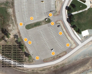
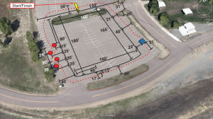
AVC 2013 Waypoints v1
The competition began. I was in heat 8, so I had a good 45 minutes to tinker before my first run. I mounted a GoPro and double checked my way pints on Google Maps. I was kind of pleased to see that almost no one in the first few heats made it past the first corner. In fact by heat 8, I think only 2 robots had made it round the course, out of about 30.
It was time for my first run. I was actually nervous !? Even thought I knew I wouldn’t win, I wanted to make it round the course, and not look like an idiot. Also I was the only Brit in a sea of Yanks … I need to represent my country ! 🙂
The countdown began, then Go! I pressed the big red button and my bot shot off ! To my surprise and great relief in the right direction !!! and to my amazement, it made the first corner and turned 90 degrees at exactly the right waypoint, on to the second straight. My heart was pounding as my bot swerved to the 2nd way point. I had 3 waypoints on the second straight to avoid the barrels. It swerved and missed the first barrel, I was actually amazed it was working !
I turned again and aimed to miss the second barrel … but then it didn’t straighten up and started to veer in to the centre of the course … within a few seconds it had hit the boundary fencing, and toppled over. Disaster! I was out in the first round mid-way up the second straight.
Not bad all things considered. Seeing as it was the first time all that code had run at the same time, completely autonomously. Although I was disappointed, I was actually quite chuffed it had made the first corner and hit the first three waypoints. My code was working !
During the beak between rounds I debugged the code and analysed the log from the first run. The bot was working, but was veering to the left, so I adjusted the 3rd waypoint to pull the bot further in to the centre of the course.
The second round. Go! I hit the button and my bot shoots off in the right direction again, but where it had neatly turned 90 degree at the first way point on the first round, this time, it span in circles at the first way point, driving in endless circles until it hit a hay bail.
In theory that shouldn’t be possible. The code should have dropped out of the loop when the waypoint was close, plus the circle was also tight, i.e. full lock. There must be something else wrong.
I spent lunch time debugging the logs and analysing the data. To my horror, the magnetometer was completely out of whack. It would reading north to be 90 degree from where it should be. And in various walking tests didn’t even change readings as I rotated the bot. My magnetometer reading were the plague of this project.
I decided to run another calibration over lunch, it takes a while, as I have to change some connections as I can’t do it reliably over xBee, so I run the calibration over a direct serial connection.
It took about 30 mins to complete the calibration and the bot was reading north again. I had about 20 minutes left of lunch to test on the course before the final heat. I pressed the button for a final practice and the bot shot off in the right direction, first waypoint hit, second way point hit, barrel avoided. Third way point hit, this was the furthest I’d ever got on the course. The back straight was perfect. I purposely avoided the hoop, I wanted to get round, and wasn’t so bothered about points. On the third straight, it actually hit the ramp and completed a jump, without toppling. It hit the final corner turned perfectly and flew over the finish line ! I had completed the course perfectly ! Shame it was over lunch in a practice session and no one saw ! 😦 I do have some video from the GoPro to prove it through !
I decide not to touch ANYTHING and wait for the final round. More and more bots were completing the course. Each run they were getting better. It was now or never.
Finally the third round was here. Nate (The Owner of SparkFun!) was my referee for the final round. No pressure then !?
The referee counted down 5,4,3,2,1 – Go ! I paused slightly to let the faster bots shoot off before me, to try and minimise any potential collisions. Previous rounds had a number of collisions right off the start line, where out of control bots took smaller bots out completely. I saw one completely smashed to pieces. My bot shot off in the right direction … turned perfectly on the first courser … weaved perfectly in through the barrels, detoured slightly wide at the second corner, my heart pounded as it headed for the fence, but with a meter to go, it turned sharply and headed off past the hoop. It started to oscillate on the back straight – shame I never got the PID controller tuned I thought – the bot headed straight for the cameraman on the 3rd corner, again with a meter to spare turned sharply 90 degrees and headed down the final straight … missing the jump (shame. It made it perfectly in the practice, and I could have got some bonus points). The curb of the final corner loomed, the bot shimmied perfectly round it, turn sharply on the final straight and headed for the finish line. I held my breath as the bot bounced over the finish line perfectly, running over the SparkFun GoPro that was balanced on the start/finish line capturing the action … 2 or 3 meters after the finish line it ground to a halt. I was so happy ! I think I actually kissed it (which someone caught on camera) 3 months of late nights and constant problems culminated on a perfect run on the final round. I was elated. I’ll post a video …
What’s next ?
I want to finish the bot off, even though the competition is over. Not only to have something ready if I manage to find a way to enter again next year, but also to understand what’s wrong. I still don’t fully understand why the magnetometer is so shonky. It’s not the device, I’ve tried 3 different devices, and they all do the same strange things.
At the competition, nearly all the other bots has their magnetometer in the car, on the main PCB, not floating on a broom handle above it like mine. I need to understand what my issues are.
I want to finish the PID tuning and increase the speed. The RC chassis is very fast, and I’m running at about 1/10th speed. If I can remove the broom handle, the bot won’t topple over so easily and can turn faster. I also want to include a proportional speed control so the bot accelerates fast if it’s far away and on a straight heading, then brakes to make the turn as it gets close to the waypoint.
I also want to finish the obstacle avoidance, so if I do head for a barrel, I can veer away from it.
All in all and very pleasant way to spend a weekend. I got to talk to lot of interesting people with a similar passion, I got to spend the weekend in 90 degree sunshine and I got to indulge my passion for robotics and spend the weekend geeking out … 🙂
Thanks to everyone at SparkFun for running the event and organising it so well.
Roll on AVC 2014 … 🙂
Other posts in this series :