Monthly Archives: February 2013

BalanceBot – PID Controller

A  PID Controller is a software algorithm typically used to control industrial processes. A PID Controller (Proportional Integral Derivative Controller) calculates the difference between a measured variable and a desired set point. The controller attempts to minimize the error by adjusting the input.

A good example of why a PID Controller is better than other methods of control, is an electric oven. The input is the power to the heating element, the output is the temperature and the set point is the desired temperature.

Without a PID controller, If you turn the power on and off using a simple thermostat, when the temperature of the oven reaches the set point the oven will over shoot the temperature as there is residual heat left in the heating element. If you want the temperature of the oven to be 200 degrees, and have the element fully on until it reaches 200 degrees, then turn it fully off, the temperature will overshoot to maybe 205 degrees, then slowly cool until it reached 199 degrees when it will turn fully on again, however it will take time to heat up, in which time the oven has cooled to 195 degrees, and so it repeats. The oven will oscillate between 195 and 205 degrees, and not actually be a steady 200. This is fine for cooking sausages, but no good for a delicate chemical process.

The PID Controller has three values; the Proportional, the Integral and the Derivative values, denoted P, I, and D. Heuristically, these values can be interpreted in terms of time: P depends on the present error, I depends on the accumulation of past errors, and D is a prediction of future errors, based on current rate of change. By combining the three terms continuously the algorithm maintains the desired set point with minimal errors.

Simple huh ? Well kind of… The maths is a bit complex, but again, there are existing libraries that do it for you. On the Arduino site you can download a fully working PID Controller library, to integrate in to your project : http://playground.arduino.cc/Code/PIDLibrary

The only problem is you need to “tune” a PID Controller to your specific application. The P, I & D terms will be different for an oven, chemical tank, or balancing robot. There are lots of ways of tuning a PID Controller, from mathematical, to trial and error. A control systems friend of mine recommended I try the Ziegler–Nichols method.

The Ziegler–Nichols tuning method is as follows;

  • The P, I & D terms are referred to as “gains” Kp, Ki & Kd.
  • The Ki and Kd terms are first set to zero.
  • The Kp term is manually increased until the robot reaches the ultimate gain, Ku, at which point the it starts to oscillate.
  • The oscillation period Pu is measured and used to set the PID terms as follows :
  • Kp = 0.6 * Ku
  • Ki = (2 * Kp) / Pu
  • Kd = (Kp * Pu) / 8

This isn’t perfectly tuned to our specific system, but it’s a good approximation. PID tuning is a black art that requires a lot of knowledge and skill. This will do for the time being.

I am using the tilt angle of the robot as the input and the speed of the motors as the output.

The code is quite simple. The three variables are all floating point numbers.

double Setpoint, Input, Output;

The PID object is instantiated with the three PID values I calculated from my Ziegler–Nichols tuning method

PID myPID(&Input, &Output, &Setpoint, Kp, Ki, Kd, DIRECT);

The desired set point is 0 degrees, i.e. the robot is perfectly upright

Setpoint = 0;

Then in my main loop I get the angle of the robot, run the PID compute function, and using the output set the motor speeds.

void loop() {
  my3IMU.getYawPitchRoll(ypr);
  Input = ypr[IMU_ROLL];
  myPID.Compute();
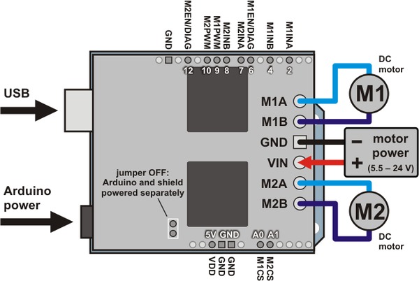
  md.setSpeeds(Output, Output);
}

That’s the theory anyway … the results were mixed. It took a number of attempts to find the oscillation gain and period (Ku & Pu) accurately. And with those values, the PID controller wouldn’t balance the robot. It took lots of manually trial and error of various values to find something that was stable. PID tuning is very much a black art.

I did get it to balance though and it was more stable that the equivalent “cubed” algorithm I was using. However with the IMU code and the PID code on the Arduino, I started getting problems with the Arduino crashing. I can only assume it was running out of RAM.

I switched to an Arduino Mega and everything worked fine. So I’ve stuck with that for the time being. The Mega is much more stable, however the custom PCBs I made don’t fit the Mega, so the wiring is messy, plus the Mega sticks out of the frame. Next job is to make the PCB as a Mega Shield and turn the board round long ways so it fits better.

The PID controller is still not perfect, but it’s relatively stable. You can see it recovers from oscillation, which the basic controller didn’t. But It still drifts badly, and still falls over eventually. But progress none the less.I need to get the Quadrature decoders working so I can stop the drifting.

Here’s a short video of the PID Controlled BalanaceBot in action.

BalanceBot – Second Steps

The second test of my BalanceBot. This time on the carpet. It drifts a lot less and is quite stable. It just has a simple “cubed” function for control. Speed = Angle ^ 3. No PID yet.

BalanceBot – First steps video

The very first time my BalanceBot balanced. It drifts quite a lot, but not bad for a first attempt. It just has a simple “squared” function for control. Speed = Angle ^ 2. No PID yet.

BalanceBot – Sensors and IMU Library

The BalanceBot needs to know if it’s upright to balance. If it starts tipping over in one direction the robot needs to sense how far it has tipped over and speed up the motors in that direction to counter the tipping motion. This will compensate for the tipping motion by driving the bottom of the robot under its centre of gravity and stand it back upright again.

Sensing the angle of the robot on a simple level could be achieved with a single g-force sensor or accelerometer. The accelerometer measures acceleration. Our planets gravity, acting on an object, is acceleration, so the accelerometer can be used to measure gravity. Gravity always pulls down towards ground at a constant value. By knowing the value you can calculate the angle of the sensor. If the sensor reads 1g, the sensor is “vertical” with the ground. If the accelerometer reads 0g the sensor is “horizontal” with the ground. By using trigonometry, the value of g can be used to calculate any angle of the sensor.

However this is only true if the sensor is perfectly still, and the only acceleration acting on it is gravity. As we are going to mount this in a moving robot, the acceleration of the robot will cause the accelerometer to read not just the gravitational force, but also any acceleration of the robot, which will render the reading inaccurate when calculating the angle of the robot.

Another method of measuring the angle of the robot is with a gyroscope. A gyroscope measures rotation velocity around an axis. If you know the angle of the sensor to start with, then continuously measure the rate at which it rotates, you can calculate the current angle. This has two issues; firstly you need to know your angle to start with and secondly any error in the calculation is compounded with time, so the calculated value “drifts” over time and become less accurate. However a gyroscope is immune to interface from acceleration.

So, if you can combine the accelerometer data and gyroscope data together you can use both readings to compensate for the inaccuracies of the other. The accelerometers can compensate for the gyroscope drift as they give exact readings at a known time. The gyroscopes compensate for the non-gravitational acceleration as they only measure rotation velocity.

This process is called “sensor fusion”. There are lots of method of processing the accelerometer and gyroscope data to give a single accurate angular reading. These include Kalman Filters and Complimentary Filters. The maths can get a bit complex but it’s all based on trigonometry. You could write your own code, but there are lots of existing, tested, libraries that do this for you.

Using such a library and the appropriate sensor can give your orientation in 3D space, your Roll, Pitch and Yaw angles, or Euler Angles. This traditionally uses an additional sensor to measure yaw, as yaw cannot be measured with a g sensor, as yaw rotates around the vertical axis, and so the force of gravity doesn’t change. The easiest way to measure yaw is with a magnetometer, this measures the earth magnetic field and can calculate your orientation to “North” (magnetic north).

BalanceBot IMU - Sparkfun 9 DOF sensor stick.

BalanceBot IMU – Sparkfun 9 DOF sensor stick.

The individual sensors all work in a single plane, so a single gyroscope only measures rotational velocity in one direction. An accelerometer only measures acceleration in one direction. Depending on how much your sensor, or robot, moves, you may need three of each sensor in each orientation (x, y & z) to calculate your orientation in 3D space. For example, as the “X” axis accelerometer rotates it will no longer be vertical and will become horizontal at which point, depending on the orientation, of the sensor either the “Y” or “Z” accelerometer begin to point down. Using 3D trigonometry of the X, Y & Z accelerometer reading, you can begin to calculate the orientation in 360 degrees. This is called “three degrees of freedom” you are measuring 3 independent parameters that define its orientation. If you add three gyroscopes, and three magnetometers, you end up with 9 Degrees of Freedom, or 9DOF.

Using a 9DOF sensor and a maths library, you can calculate (almost) any orientation accurately. This combination of sensors and maths is called an Inertial Measurement Unit or IMU. There are lots of these, ranging in accuracy and cost. They can cost thousands of pounds. However there are lots of hobby level devices too for less than £100.

You have the choice of separate sensors and use your own CPU for the maths, or use an all in one device that includes its own CPU. I have an UM6-LT Orientation Sensor from CH Robotics for a different project. They are easy to interface to and do all the Kalman filtering for you on board and provide the filtered, stable Euler Angles via a serial interface. However I was using this device in a different project.

There are many 9 DoF boards containing just the sensors. FreeIMU is a popular board, cheap and compact. SparkFun produce a 9DoF Sensor Stick which I decided on, as its cheap, small and easy to interface to.

The FreeIMU site provides a GNU GPL license library for Arduino which supports not only the FreeIMU boards but also the SparkFun boards and the DIYDrones ArduIMU. This provided the sensor fusion calculations to provide a stable combined output from the raw sensors.

The SparkFun board uses an I2C interface to communicate with the Arduino. This is a bidirectional serial interface, using just two data wires, and power.

To be clear I didn’t need a 9DOF board in this simple robot, as I only needed to calculate the robots orientation in one axis (the axis that rotates around the wheels) however, by using a 9DOF board I get full 3D orientation which means it doesn’t matter which direction I mount the sensor in, plus I intend to use the magnetometer reading to capture the “heading” the robot is traveling on so I can make it travel in a straight line. It was also fun to learn.

There are two common ways to represent a 3D orientation; Euler Angles and Quaternions.

Euler Angles can be understood easily if you imagine an old fashioned gyroscope in an aeroplane. A spinning mass is suspended in space on 3 gimbal bearings, that each rotate in a perpendicular axis. As the aeroplane tilts left and right (rolls) the gimbals rotate to keep the mass level. This angle of roll is the Roll Euler Angle. Same for Pitch, the movement of the nose of the plane up and down, and Yaw the rotation of the plane caused by the movement of the rudder. These three Euler angles define the Roll, Pitch and Yaw of the object. However Euler Angles have a flaw, as one of the axis rotates 90 degrees, it aligns with one of the other axis. In fact all three axis can align. This is called Gimbal Lock.

Gimbal lock is the loss of one degree of freedom in a three-dimensional space that occurs when the axes of two of the three gimbals are driven into a parallel configuration, “locking” the system into rotation in a degenerate two-dimensional space.

This means in some situations Euler Angles cannot accurately define our orientation. However they work fine for movements that do not exceed 90 degree rotations, which is our case if fine, as we will only be “wobbling” a few degrees from vertical. (I hope)

An alternative system is called Quaternions which does not suffer from Gimbal Lock. This uses imaginary numbers to define our three dimensional orientation, and is way too complex to try and explain here. Plus I don’t really understand it enough 🙂

So, I stuck with Euler Angles.

The FreeIMU library provides a simple function to calculate the Euler Angles :

my3IMU.getYawPitchRoll(ypr);

This fills a 3 dimensional variable with three floating point numbers, which contains the Pitch, Roll and Yaw angles.

With my sensor mounted as it is, the “Roll” angle is the rotation around the wheels, this is the only value I use:

angle = ypr[IMU_ROLL];

With just this value I can balance the robot. If the angle is positive, I drive the wheels in one directions and it the angle is negative I drive the wheels in the other direction. By proportionally driving the wheel speed, relative to the angle, the robot balances. I tested it using a cube function. i.e. Speed = Angle ^ 3

If the angle is 1 degree, the speed is 1 (slow), if the angle is 2 degrees the speed is 8 (faster), if the angle is 3 degrees the speed is 27 (quite quick), etc. The more the robot falls over the faster the wheels rotate to stand it back up. When the robot is upright the speed is very slow so the robot doesn’t overshoot and start to oscillate.

Of course it does oscillate with this very simplistic control algorithm and falls over. We need a more complicated control algorithm to stop the oscillation.

A PID Controller works well. More on that next…

BalanceBot – Quadrature Decoders

I’m old school when it comes to prototyping. I tend to test bits of the initial circuit on a breadboard, but quickly move to a prototype board using wire wrap. I’m a big fan of wire wrap prototyping over breadboard. It has lots of benefits;

The wires in Breadboards have a tendency to fall out if moved or quickly become a birds nest if the circuit is complicated.

Breadboards don’t stack neatly like shields, so they are difficult to mount in the chassis.

I knew my Robot was going to fall over a lot initially, so I wanted something sturdy that could take some knocks, without falling part, but could be changed easily if I got something wrong (you always get something wrong)

I found some great prototyping boards from FreeTronics.com (ProtoShield Pro for Arduino). These have a reset button, a general purpose button and general purpose LED mounted around the edge of a grid of holes. This is great for prototyping. The boards are well designed with easy access to power rails and they’re cheap.

I buy long pin through hole sockets for wire wrap and solder just two legs of the socket (at diagonal corners) on to the prototype board, just to hold the socket in place. You then use special thin wire wrap wire and a tool that twists the wire on to the pin, to wire your circuit. There’s no soldering to wire the circuit (just a dab to hold the socket on to the board) the friction of the wire wrapped around the pins holds it tight. You can cut the wire to roughly the right length for each connection, so the board stays tidy and does not resemble a birds nest.

Quadrature Counter Shield

Quadrature Counter Shield

If you make a mistake, you can use the tool to unwrap the wire and you just replace it with the correct connection. Once the circuit is complete, the board plugs in as a normal shield, and it’s robust enough not to fall apart in use.

The LS7366 Quadrature Decoders are chips made by LSI. There is a decoder IC for the quadrature encoder on each motor. The ICs have a 32 bit counter, so they can count about 4,294 million pulses before rolling over. They have an SPI interface so it’s just 5 wires to connect them both to the Arduino (three common SPI data lines and two slave select lines). The SPI interface uses common data and clock lines from every device (slave) to communicate to the Arduino (master). The master controls who can talk on the data lines, through a unique Slave Select (SS) line connected to each device. When the slave select line is held low that device talks to the master. When the slave select line is high, the slave ignores the data lines and puts the pins in a “high Z” state, i.e. they are isolated from other signals or devices connected to the common data lines.

  • MISO – Master In Slave Out (data from the chip to the Arduino)
  • MOSI – Master Out Slave In (data from the Arduino to the chip)
  • SCK – Clock

These three lines are all connected in parallel.

  • SS – Slave Select is unique to each slave and is connected back to a separate pin on the Arduino.

In this case, I used Arduino pins 3 & 5 for the two quadrature decoder slave select lines (one for each motor). The SPI data and clock pins are pins 11, 12 & 13 on the Arduino.

LS7366 Quadrature decoder shield schematic

LS7366 Quadrature decoder shield schematic

I had a few issues with the wire wrap prototype, misreading my own initial circuit diagram, but I soon got it working.

The code is simple, but understanding the data sheet took some time. To setup SPI on the Arduino, you have to set three parameters, the Mode, the Bit Order and the Clock Frequency. They are all defined in the data sheet for your device.

The mode sets the phase of the signals for valid data, i.e. does the device response on rising or trailing edges of the clock. Wikipedia has a very useful entry on SPI : http://en.wikipedia.org/wiki/Serial_Peripheral_Interface_Bus

The Bit Order defines whether binary numbers are sent down the serial interface most significant bit first, or least significant bit first.

The Clock Frequency in the Arduino library is a multiple of the system clock. The maximum clock rate your device can handle will be in the data sheet. Then it’s just some simple maths to work out what multiple of the Arduino 16MHz clock you need to not exceed the maximum clock rate for your device. In this case I’m using “divide by 8” i.e. 2 MHz

There is an SPI library in the Arduino, which makes all this easy.

SPI.begin();
SPI.setDataMode(SPI_MODE0);
SPI.setBitOrder(MSBFIRST);
SPI.setClockDivider(SPI_CLOCK_DIV8);

To send data to and from the device you call the “Transfer” function while holding the correct Slave Select line low :

SPI.transfer(byte val);

This sends a byte (8 bits) out of the SPI bus. You’ll notice all SPI communications are 8 bits. Our counter is 32 bits, so I wrote some helper functions to read the 4 byte counter values. You just need to read the multiple bytes sequentially.

Here’s the helper function that reads the 32 bit counter values, which takes the slave select line as a parameter, so I can use it for either quadrature counter. It sends the read command and then reads 4 bytes in sequence, building them in to a 32 bit unsigned long.

#define  RD_CNTR B01100000
unsigned long ReadCounter(byte CSx)
{
  unsigned long result;
  byte b;
  digitalWrite(CSx,LOW);
  SPI.transfer(RD_CNTR);        // Read CNTR
  result = 0;
  b = SPI.transfer(0x00);
  result = result | b;
  result = result << 8;
  b = SPI.transfer(0x00);
  result = result | b;
  result = result << 8;
  b = SPI.transfer(0x00);
  result = result | b;
  result = result << 8;
  b = SPI.transfer(0x00);
  result = result | b;
  digitalWrite(CSx,HIGH);
  return result;
}

I don’t actually need the quadrature counters in phase one of the project to get the BalanceBot balancing. It will balance without them. However, it will probably drift from its original position as its balancing. The plan is to count the quadrature pulses as it drifts and then bring it back to its original position once it’s stable. This should mean if the robot gets knocked, it will move back to rebalance, and then slowly come back to where it was, maintaining its position.

Quadrature Counter Shield

Quadrature Counter Shield

Once I got the wire wrap version working, I converted the board to a custom PCB using Eagle PCB software and BatchPCB. More on that later…

BalanceBot – Motor Controller

I used a Pololu Dual VNH5019 Motor Driver Shield for Arduino as the motor controller. It has two VNH5019 MOSFET H-Bridge brushed DC motor controller IC’s mounted on an Arduino Shield. The motor controller can drive up to 12A continuous current per motor, 30A maximum. The motors are controlled via a PWM signal generated by the Arduino, and sent to the controller ICs, which in turn drive the MOFETS to control the speed and direction of the motors. The controllers can work up to 24v, but we are using 12v motors with a stall current of 5A, so the controller shouldn’t even break in to a sweat.

VNH5019 Shield

VNH5019 Shield

The shield comes with an Arduino library, making the programming simple. There is a function setSpeeds (int m1Speed, int m2Speed); which takes an integer speed for each motor, from +400 (full speed ahead) to -400 (full speed reverse), with 0 being stop.

There are quite a few other functions on the controller including braking and current monitoring, but I doubt we’ll use them in this project.

The only down side of using this particular shield is it takes lots of IO pins. There is a PWM signal for each motor, direction indicators, the current sensing output, enable lines and error signals. All in all the shield uses 10 IO pins of the 20 pins in total. This isn’t a show stopper, we still have enough left over (just) but there is one problem.

The shield uses pin 12 for the M2EN signal. We need pin 12 for SPI. The SPI signals are pins 11,12 & 13. There is the feature on the board to cut the track for control signals so you can move them. I had to cut the track and solder a thin wire from the jumper to the new pin. I picked pin A2 as we don’t need that and I updated the library with the new pin details.

VNH5019 Shield Schematic

In the library source code (arduino-1.0.x\libraries\DualVNH5019MotorShield\DualVNH5019MotorShield.cpp) just chnage the default constructor code to use the new pin :

DualVNH5019MotorShield::DualVNH5019MotorShield()
{
  //Pin map
  _INA1 = 2;
  _INB1 = 4;
  _EN1DIAG1 = 6;
  _CS1 = A0;
  _INA2 = 7;
  _INB2 = 8;
  _EN2DIAG2 = A2; // = 12;
  _CS2 = A1;
}

The controller worked fine first time. It’s powered directly from the battery. There is a jumper on the shield to power the Arduino from an on board regulator, so the motor battery powers the Arduino too. The library makes programming easy, and the motors are fast and responsive. The only thing you need to remember to do is wire one of the motors to the shield in revere. For the robot to travel forward with both motors at “+400”, one motor needs to be wired in reverse to the other as they are on either sides of the robot, clockwise is forwards for one motor, and anti-clockwise is forwards for the other. This doesn’t affect the motors at all, and it makes the code slightly easier to read.

BalanceBot – Components

The main components for BalanceBot are :

  • Two geared motors with quadrature encoders
  • A Motor controller
  • An Arduino Uno for a brain
  • A 9 DoF sensor stick to provide the IMU
  • A custom board to interface the quadrature encoder counters
  • A 12v rechargeable battery.

The motors are Pololu metal gear motors and Pololu have a nice motor controller shield that matches the requirements of the motors. The motor shield has a built in regulator to power the 5v Arduino from the motor power coming from the battery, so I could power everything from a single 12v rechargeable battery. A perfect fit. Pololu also sell mounting brackets for the motors and wheels. So that’s the mechanics covered in a single order.

The brain is an Arduino Duemilanove with an ATmega328p microcontroller but this is essentially the same as the newer Arduino Uno.

I read a lot about various IMUs and considered using an all-in-one unit with a built in CPU and code. I have an UM6-LT Orientation Sensor from CH Robotics for a different project and they are easy to interface to and do all the Kalman filtering for you on board, but I needed it for the other project, and they’re expensive, so I decided to use a raw 9 DoF sensor board and do the data fusion and filtering in code on the Arduino.

These 9 DoF boards are cool from FreeIMU but at the time I was researching this, there weren’t many online stores selling them, so I decided to use a SparkFun Sensor Stick. The FreeIMU site provides a GNU GPL license library for Arduino which supports not only the FreeIMU boards but also the SparkFun boards and the DIYDrones ArduIMU.

I was hoping to find an existing 3rd party Quadrature decoder Arduino shield, but I couldn’t one. I found some quadrature counter ICs LS7366 with an SPI interface. These count the quadrature pulses from the motors so the Arduino can read the count totals using SPI. I prototyped a shield for them using wire wrap and then manufactured a custom PCB using BatchPCB.com.

The frame is made from MicroRax which gave me the flexibility to build the frame to any dimensions to mount the motors and controller boards. Its strong and easy to construct and it also meant I could change my mind 🙂

The other components are from Maplins. A standard sealed 12v battery and some switches.

Finally, to make it look more professional I have some custom acrylic sheets laser cut for the base and top. These made mounting the PCBs and switches easier and made it look less Heath Robinson.

A sad note, Fabio Varesano (http://www.varesano.net/) the 28 year old student behind FreeIMU died suddenly over Christmas last year. Such a terrible shame for such a talented young man. He invested so much effort designing and developing FreeIMU and provided lots of support and encouragement to the robotics community. The information from his site was part of my research for this project and I’m sure he will be missed by the community. My heartfelt sympathy goes to his family and friends.

BalanceBot – My First Post

The plan for BalanceBot is a two wheeled self-balancing robot. I’ve always wanted to build one since school, but never got around to it. The robot consists of some distinct building blocks and could be described as just a system integration project :-). However the project gave me the opportunity and motivation to play with a number of technologies I’ve not used in a while. Specifically, I wanted to understand IMUs & Kalman Filters and PID Controllers. The maths can be very complex, but I like a challenge. I also discovered Quaternions, while researching IMU’s, which I never even knew existed. Don’t you love learning new stuff !? 🙂

BalanceBot

BalanceBot

I’ve never had a custom PCB made by a fab house before, I used to etch my own years ago but the technology has become more accessible since then, the costs are tiny and there’s great free software. I’ve also never had anything laser cut and this was a great opportunity to learn about the tools and process. So all in all, a project I’ve always wanted to build, with lots of cool new tools to play with and learn. Last but by no means least, I’ve never blogged before. I don’t even tweet. So, I thought I’d start a blog about the BalanceBot build and then continue it for my other tinkering projects.

Quite a lot of goals in a single project. The first challenge is time. I don’t have much spare time, so what should have taken me a couple of weeks, took months, with just a few hours each weekend and nothing in the middle. The blog plan didn’t work either, as instead of blogging as I went along, I kind of saved everything up until the end.

But here goes…