
I used a Pololu Dual VNH5019 Motor Driver Shield for Arduino as the motor controller. It has two VNH5019 MOSFET H-Bridge brushed DC motor controller IC’s mounted on an Arduino Shield. The motor controller can drive up to 12A continuous current per motor, 30A maximum. The motors are controlled via a PWM signal generated by the Arduino, and sent to the controller ICs, which in turn drive the MOFETS to control the speed and direction of the motors. The controllers can work up to 24v, but we are using 12v motors with a stall current of 5A, so the controller shouldn’t even break in to a sweat.
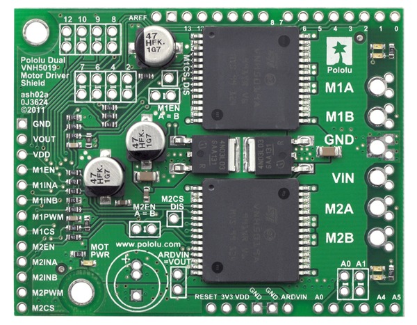
VNH5019 Shield
The shield comes with an Arduino library, making the programming simple. There is a function setSpeeds (int m1Speed, int m2Speed); which takes an integer speed for each motor, from +400 (full speed ahead) to -400 (full speed reverse), with 0 being stop.
There are quite a few other functions on the controller including braking and current monitoring, but I doubt we’ll use them in this project.
The only down side of using this particular shield is it takes lots of IO pins. There is a PWM signal for each motor, direction indicators, the current sensing output, enable lines and error signals. All in all the shield uses 10 IO pins of the 20 pins in total. This isn’t a show stopper, we still have enough left over (just) but there is one problem.
The shield uses pin 12 for the M2EN signal. We need pin 12 for SPI. The SPI signals are pins 11,12 & 13. There is the feature on the board to cut the track for control signals so you can move them. I had to cut the track and solder a thin wire from the jumper to the new pin. I picked pin A2 as we don’t need that and I updated the library with the new pin details.

- VNH5019 Shield Schematic
In the library source code (arduino-1.0.x\libraries\DualVNH5019MotorShield\DualVNH5019MotorShield.cpp) just chnage the default constructor code to use the new pin :
DualVNH5019MotorShield::DualVNH5019MotorShield()
{
  //Pin map
  _INA1 = 2;
  _INB1 = 4;
  _EN1DIAG1 = 6;
  _CS1 = A0;
  _INA2 = 7;
  _INB2 = 8;
  _EN2DIAG2 = A2; // = 12;
  _CS2 = A1;
}
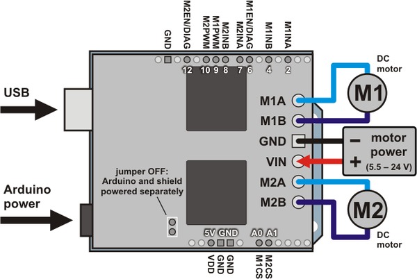
The controller worked fine first time. It’s powered directly from the battery. There is a jumper on the shield to power the Arduino from an on board regulator, so the motor battery powers the Arduino too. The library makes programming easy, and the motors are fast and responsive. The only thing you need to remember to do is wire one of the motors to the shield in revere. For the robot to travel forward with both motors at “+400”, one motor needs to be wired in reverse to the other as they are on either sides of the robot, clockwise is forwards for one motor, and anti-clockwise is forwards for the other. This doesn’t affect the motors at all, and it makes the code slightly easier to read.
