
Once the initial Arduino prototype was built I started having problems with the board. I rigged it on the bench with two servos attached directly to the speed and steering outputs. The code kept crashing and the board would hang. Normally in strange ways. I would comment out lines of code, and it would be more stable, then I’d put different code in and it would crash again. It seemed to have little to do with the content of the code, and more to do with the *amount* of code…
I had this problem before with my balance bot. The code randomly crashed there too and if you run some basic compiler tools on the code, the code is very close to the RAM limit of the microcontroller.
I had been looking at mBed for a few months and had bought a board to play with and this seemed like a perfect project to learn mBed on. I could have switched to an Arduino Mega, which is what I did on my Balance Bot, but the Mega is physically so much larger, and I wanted to fit the resulting controller inside the RC car, so I bit the bullet and scrapped everything I’d done to date, and started again with mBed. There’s nothing better than a looming deadline and nothing currently working to focus the mind on learning a new platform. 🙂
I had an LPC1768 mBed which had much better specs. I would classify its advantages over Arduino as :
- Faster – 100 MHz vs. 16 MHz. Six times more instructions per second means more power. I could read the GPS and magnetometer at a much faster frequency and baud giving me better accuracy and control.
- More hardware serial ports – 1 UART on the Arduino vs. 3 UARTs on the mBed – I needed a fast serial port for the GPS and one for debugging via xBee.
- Hardware I2C for the magnetometer.
- More RAM (32 KB vs. 2KB on the Arduino) more than enough to run all the various libraries and calculations without crashing.
- Hardware floating point – This is important for GPS as the LAT/LON coordinates are all floating point numbers. There would be lots of complex trigonometry with floating point numbers happening every second. Hardware floating point would be a huge improvement in performance.
- The last benefit was unexpected. The mBed has an RTOS library that allows you to run multiple independent threads. This made the code design much simpler. Rather than having one big main loop, that has to do everything, I could split up the tasks in the threads. E.g. one just ingesting and parsing GPS NEMA data, one outputting debug information, one running the PID control loop, etc.
The design changed from Arduino to mBed over night and I planned a new board. Although this has only taken a couple of blog pages to explain, it took about 6 weeks in elapsed time. Lots of late night debugging, scratching my head, reading on the interweb and chatting to people on forums.
I designed another PCB for the mBed solution and using the cheap PCB fabs I calculated it would arrive a couple of weeks before the competition. I had no choice but to commit to this design. There would be no time to reinvent the solution a third time. In fact if it didn’t go well, I’d be soldering it on the plane, if I wasn’t lucky … 🙂
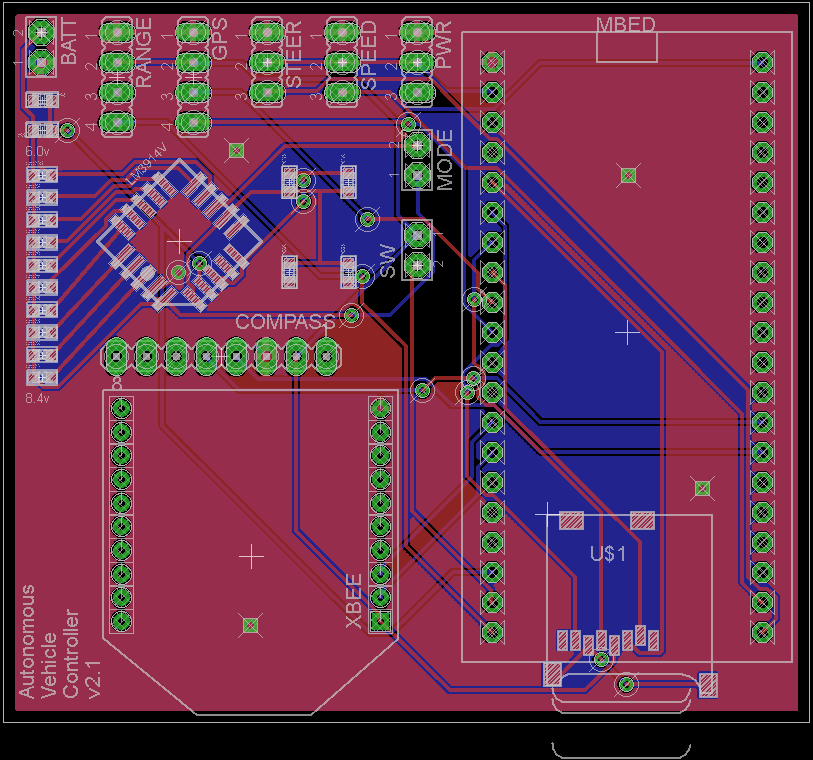
AVC 2013 mBed Custom PCB v2.1 layout
I added a battery meter to the final PCB design as a last minute addition. I had seen this video on the EEVblog describing the LM3914 LED driver. The worked example on the video was exactly what I needed to monitor the charge of my LiPo’s, so I added the circuit and LEDs to the final PCB. This would give me an easy visual reading of the battery condition before each run, reducing the risk of the run failing due to a low battery. In retrospect, I perhaps should have done this a different way. The LED driver was actually more complex and more expensive that driving the LEDs from the mBed directly. I have enough IO pins and I’m already taking an ADC reading of the battery voltage, but it seemed like a good idea at the time.
I sent the PCB design off which would give me a few weeks to convert the code.
I should point out here why I like having custom PCBs, instead of wire wrap or breadboards. I do jump to custom PCB very quickly in my prototyping phase. The simple answer is reliability. In the past I have run projects from a breadboard. But as always happens you drop the project, or it has to travel somewhere in a box, and suddenly two of the wires have popped out of the bread board. Typically you now waste hours tracing every connection to work out where they went and which ones have popped out. Plus with moving robots, the momentum of the bot tends to throw the boards around unless they are stuck down well, giving the same problem with wires coming lose. I like having a custom PCB. They are very cheap and easy to make (once you’ve used Eagle a few times) and they make the circuit an order of magnitude more reliable, much smaller and less messy. In addition they are just as easy to change if something is wrong, you can cut a trace and solder in a jumper wire in. Plus things like xBee, which has 2mm pitch legs, aren’t breadboard friendly, so you end up with breakout boards, again that come lose. Custom PCBs are just easy, cheap, and more reliable.
I started by porting the existing Arduino GPS and magnetometer libraries to mBed, which meant the bulk of my code would just migrate to the new platform. The mBed platform is fantastic. Its “proper” C++, not the cut down libraries of Arduino. I got things like printf back 🙂 which are huge resource hogs on Arduino.
There were other benefits too. There is a simple SD Card library, so I could store my waypoints on an SD card, which would mean making small edits during the competition wouldn’t mean I needed to recompile the code and upload it to the mBed, I could just edit the text file in an editor and re-read them.
I structured my code slightly differently to make use of the multithreading benefits of mBed too. I had three threads;
- The first was dedicated to just ingesting the GPS NEMA strings and converting them in to numbers that were stored in a global variable structure. I ran the GPS at 4 Hz to give me good accuracy.
- The second thread was dedicated to providing debug data. It ran every second, (or every 2 seconds) and dumped all the current readings of all the sensors and internal variables over the xBee. These would then be read by the desktop app and displayed in a user friendly way.
- The final thread was the main loop. This ran the PID control and used the data from the GPS structure and magnetometer to feed the PID, and then set the steering servo with the output of the PID.
I got a prototype working on an mBed development board while I waited for the custom PCB to arrive. I used wire wrap as usual, with some jumper leads to plug in to the mBed. The prototype worked OK and I started to get a basic system working.

AVC 2013 mBed wire wrap prototype

AVC 2013 mBed wire wrap prototype
Here’s the test video the full system working on the bench for the first time. You can see the third channel switch the control between RC and mBed. During mBed control, the compass on the mBed controls the steering servo, and the wheels track the position of the compass. During RC control, the transmitter has control and the mBed does nothing.
Other posts in this series :
- AVC – It’s ready !
- AVC – How difficult can it be ?
- AVC – Switching from Arduino to mBed
- AVC – Problems
- AVC – First test run
- AVC – Competition Day
