
The Sparkfun Autonomous Vehicle Competition this year was lots of fun, as usual. I ran a similar setup to last year, with the same chassis, mBed microcontroller, Magnetometer & GPS. The only difference was a new controller PCB with some extra features, and some changes in the code. The new control board has some incremental improvements from last year, with on-board battery monitor, better layout, built in Mux to multiplex RC and Autonomous control, and an on-board RS232-TLL converter (MAX3221).
AVC 2014 controller PCB v3.2
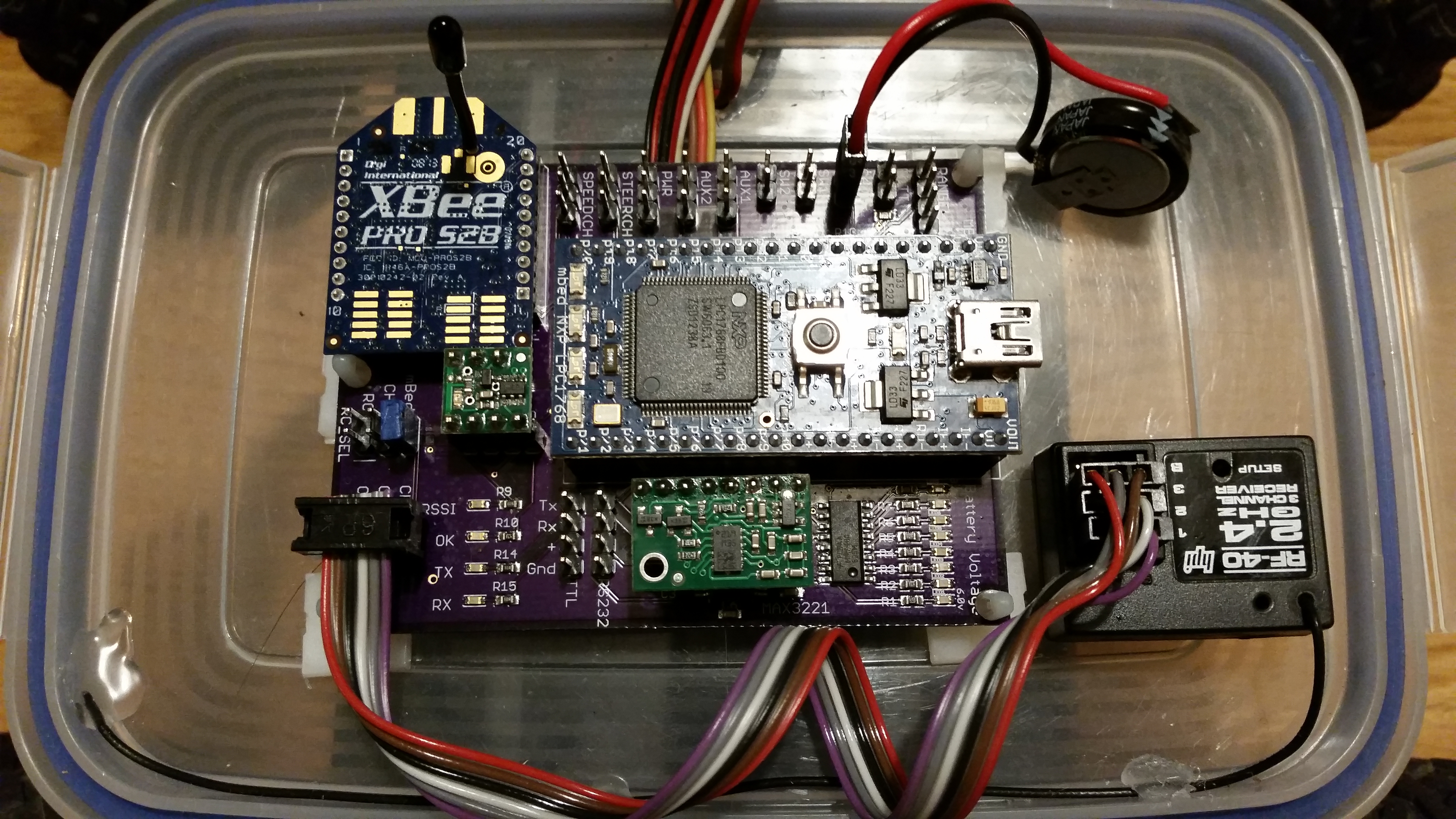
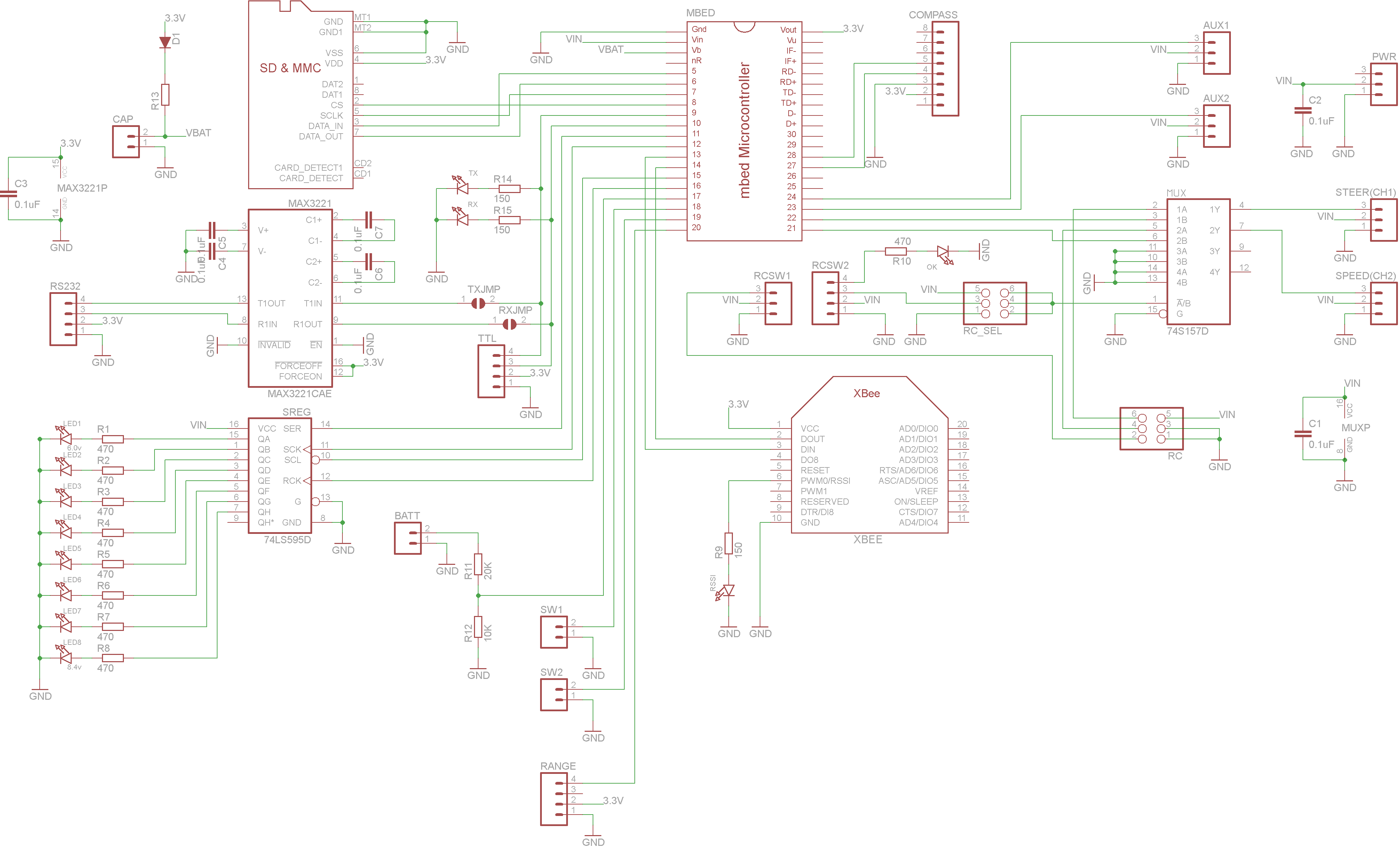
AVC 2014 controller board v3.2
The battery monitor uses a shift register to control the 8 LEDs, so I only need 4 IO lines to control 8 LEDs. The mux uses a 74S157D to multiplex the PWM lines from the RC receiver and mBed out to the RC car steering servo and speed controller. By changing the mux select line, I can control the RC car from the RC controller or the mBed, either forced with a jumper (RC_SEL) or by using channel 3 on my RC transmitter. To decode the channel 3 signal and give me a digital output I use a Pololu RC Switch with Digital Output.
The other useful addition was a 1F super capacitor, attached to the vBAT pin on the mBed. One problem from last year was that all my log files were dated “1/1/1970” as when the mBed boots the clock isn’t set, and I create the log file on boot. I set the clock once I have a GPS lock, with the time from the GPS, but until I have GPS lock, I don’t know what the time is. The mBed has a real time clock, I just need to keep it powered between power downs.
Supplying 3.3v to vBAT keeps the RTC running, even when the main power is off. Usually, you would use a small lithium coil cell, but I had just bought some super caps to play with and they seemed perfect. I used a diode and resistor from the 3.3v power rail to charge the super cap while the power is on and limit the charge current. It works perfectly and kept the clock running for days while the main power was discounted. Now, all my log files have the correct date and time, and once I get a good GPS lock, I reset the RTC, just in case it has drifted.
The bot was ready a couple of weeks before the competition, but as usual, I didn’t have time to do much testing, and my flight only got in to Boulder the night before the competition, so I couldn’t spend the day before at the course. The day of the competition arrived and I got there early to setup and do some last minute testing.
I was in group 7 of the Peloton class. Team : “Mostly Robots”. Robot : “Eleanor”.
There are 3 heats (3 attempts at the course). The are timed, with bonus points for navigating obstacles.

AVC Ground Course ((c) Sparkfun)
Heat 1
Heat 1 got off to a good start. I’m always apprehensive as the bot approaches the first corner. Anyone can build a bot that just drives in a straight line and crashes in to the fence. Turning at the first corner autonomously is a good feeling ! 🙂 The bot was swerving badly on the straight, more than last year. Same old magnetometer issues from last year, but it turned perfectly on the 1st corner. Its programmed to avoid the barrels and zig-zag through them, which it did, and made the 2nd corner. However on the 3rd straight it started to wobble more and zig-zag quite badly instead of driving in a straight line. It made the 3rd corner, but then started to get a bit confused. It spun round in circles a couple of times, then crashed in to a bollard. Disappointing, but not bad for a first run.
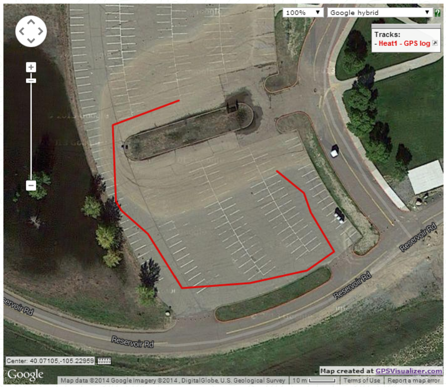
AVC 2014 – Heat 1 GPS log
Heat 2
The less said about heat 2 the better :-). It all went wrong, and straight off the start line the bot crashed in the kerb.
Heat 3
Heat 3 started well, the bot made the 1st corner, avoided the barrels and made the 2nd corner. But on the back straight got confused again and crashed in to the kerb.

AVC 2014 – Heat 3 GPS log
In the end, a fun but disappointing day, as I know the bot can navigate autonomously, as it makes it round three quarters of the course, but the gremlins stopped me from completing all of the three heats.
I came 14th overall out of 25 in my class. Respectable, but I could have done better.
The problem is always the magnetometer. I need to find some time before the next event to work on fine tuning it and experimenting with some different positions to stop interference from the car’s motor and servos.
Roll on next year ! 🙂

Hi there, Your post was pretty interesting to read. Hope you are making progress for the next year. I am finally at the stage of developing the PI controller for the steering, and was having issues with the steering control close to 0 degrees.
Basically the fact that the magnetometer value oscillates between around 0 and 359 makes the error value for the controller go from ~ 0 to to ~ 359. This is making my control output vary widely at that operating point. Have you come across this issue?
I am recording my learnings on my blog: rudraxx.wordpress.com
Thanks,
Abhi
Hi. I adjust the magnetometer output to read -180 to +180, not 0-360, so around 0, it reads +1 and -1 … this stops the PID control going bananas.