
I have several QNAP storage arrays at home. I store my Photos, Videos, MP3 collection and DVDs, etc, on them. I usually have two running at any one time and they usually mirror each other, so I have two copies of all my data at home at any time. I also backup to cloud storage and try and follow the “3-2-1 backup policy” – 3 total copies of your data, stored on 2 different types of media, with 1 copy kept off-site – to provide good resilience in the event of a major incident or failure.
However, recently I’ve been using them for other things, specifically storing my security camera footage, and other less important things, and the two live units I currently have are nearing capacity.
While rummaging through the loft a few weeks ago, I noticed that my old, retired QNAPs are still in the loft, powered down and collecting dust. I have three old 4-bay units (2 x TS-412 & 1 x TS-410), which are long since out of support, and no longer get updates or patches. The TS-412 was released in 2009, and served me well, I probably got 15+ years of life out of them. They finally went End Of Life on 31 December 2020, and I replaced them with two TS-431KX. I’ve had these for a few years now too, and even they are classed as “legacy”, so I expect them to go EOL soon.
The motherboards in the TS-410 & TS-412 look identical. The specification on the QNAP Site (TS-410 & TS-412) suggest the only difference is a slightly faster SoC in the TS-412. 1.2 GHz in the TS-412 verses 800Mhz in the TS-410. I suspect the same motherboard is used in other models, but I dont have access to any. Feel free to contact me if you find other QNAP models that use the same motherboard, that this conversation will also work with.
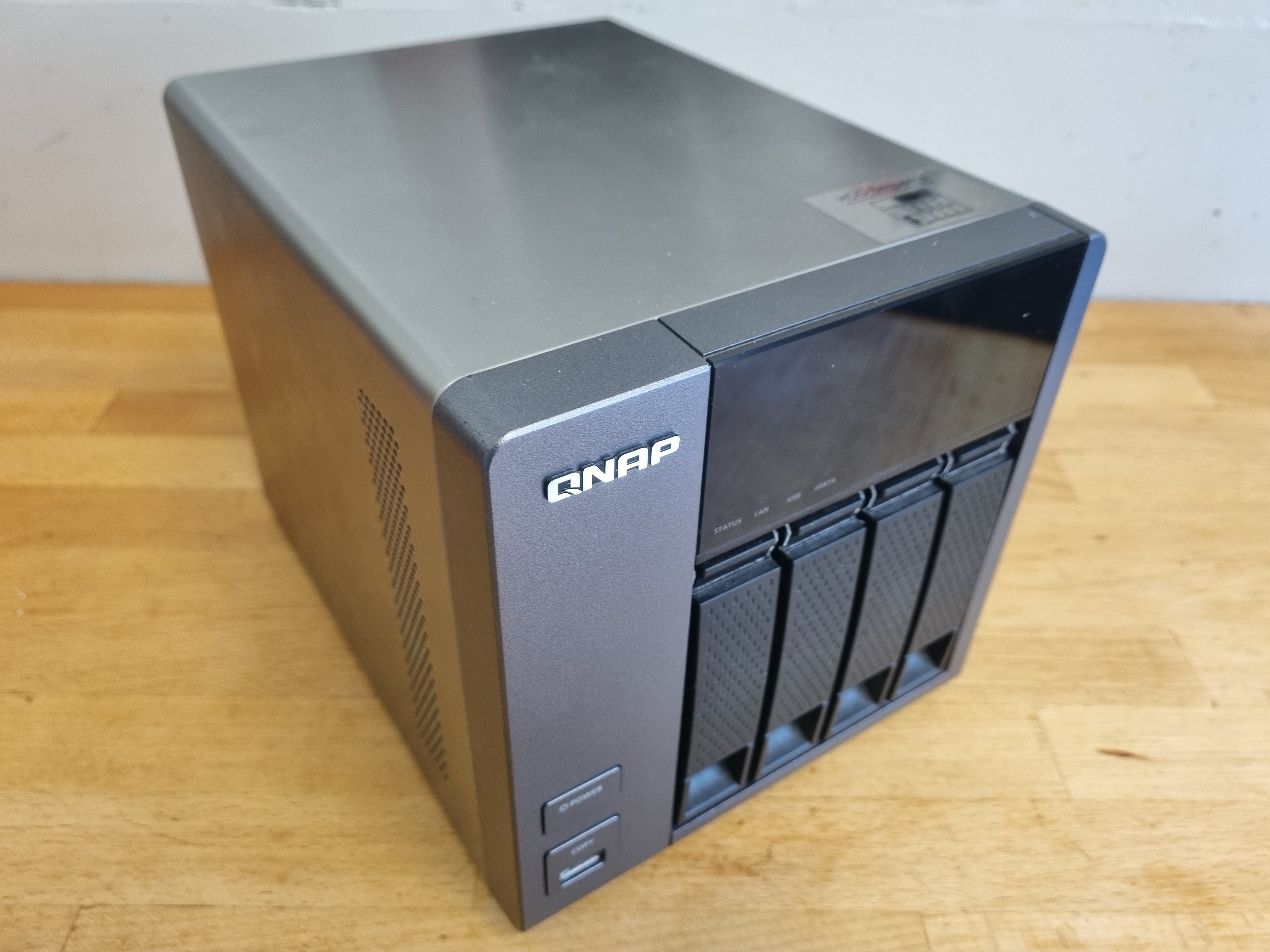
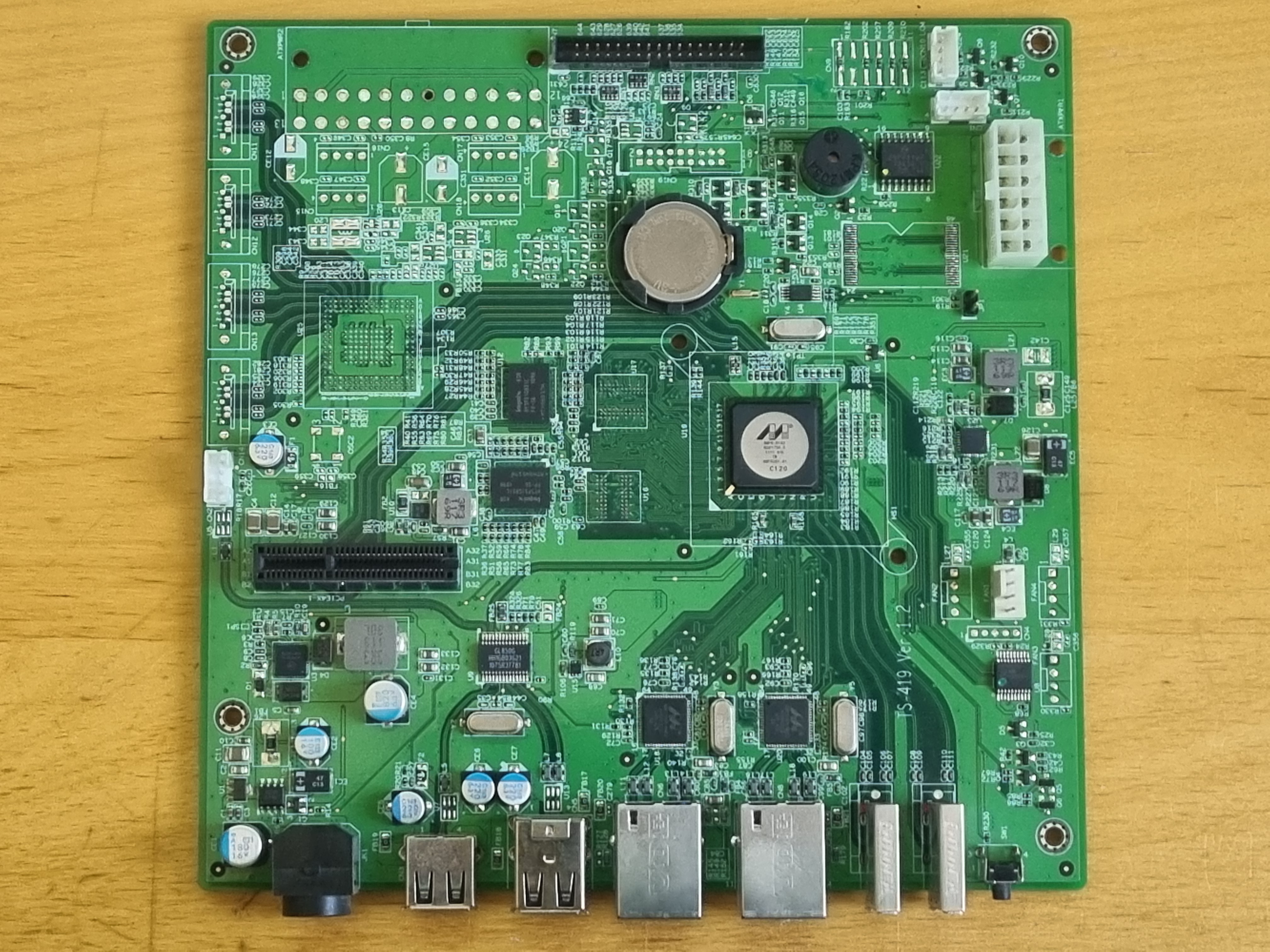
So, I had the brilliant idea to upcycle my old TS-412 devices to see if I could migrate them to use open-source software so I could squeeze more life out of them, than the manufacturer wants to support. It seems wasteful to replace them every 5 or 10 years, just because the software is no longer supported. The form factor is perfect. They are small and quiet and hold four full sized hard disks. I even have the old 3TB Seagate drives in them, so if I manage to upcycle them I could resurrect 18-24TB of storage!
Initially, I planned to try and get Linux to run natively on the existing hardware. I took one apart to get all the hardware specs and investigate the internals. The motherboard is based around a Marvell 6281 1.2GHz Arm CPU, with 256MB DDR2 RAM, 2 x Gigabit ethernet ports, and 4 x USB 2.0 ports. I could probably get Linux to run on this hardware, but its not particularly performant and shows the age of the 15 year old hardware. 256MB of RAM will be a challenge, even for Linux, and it does not have a standard bootloader.
However, I noticed that the SATA backplane connects to the old motherboard with what looks like a PCI connector. Once I had the backplane card out completely, I traced the pins and pads and compared it to the PCIe standard, and it looked similar, in fact I was confident it was a valid PCIe connection. The SATA Controller IC on the backplane is a Marvell 88SX7042 PCIe 4ch SATA-II bridge.
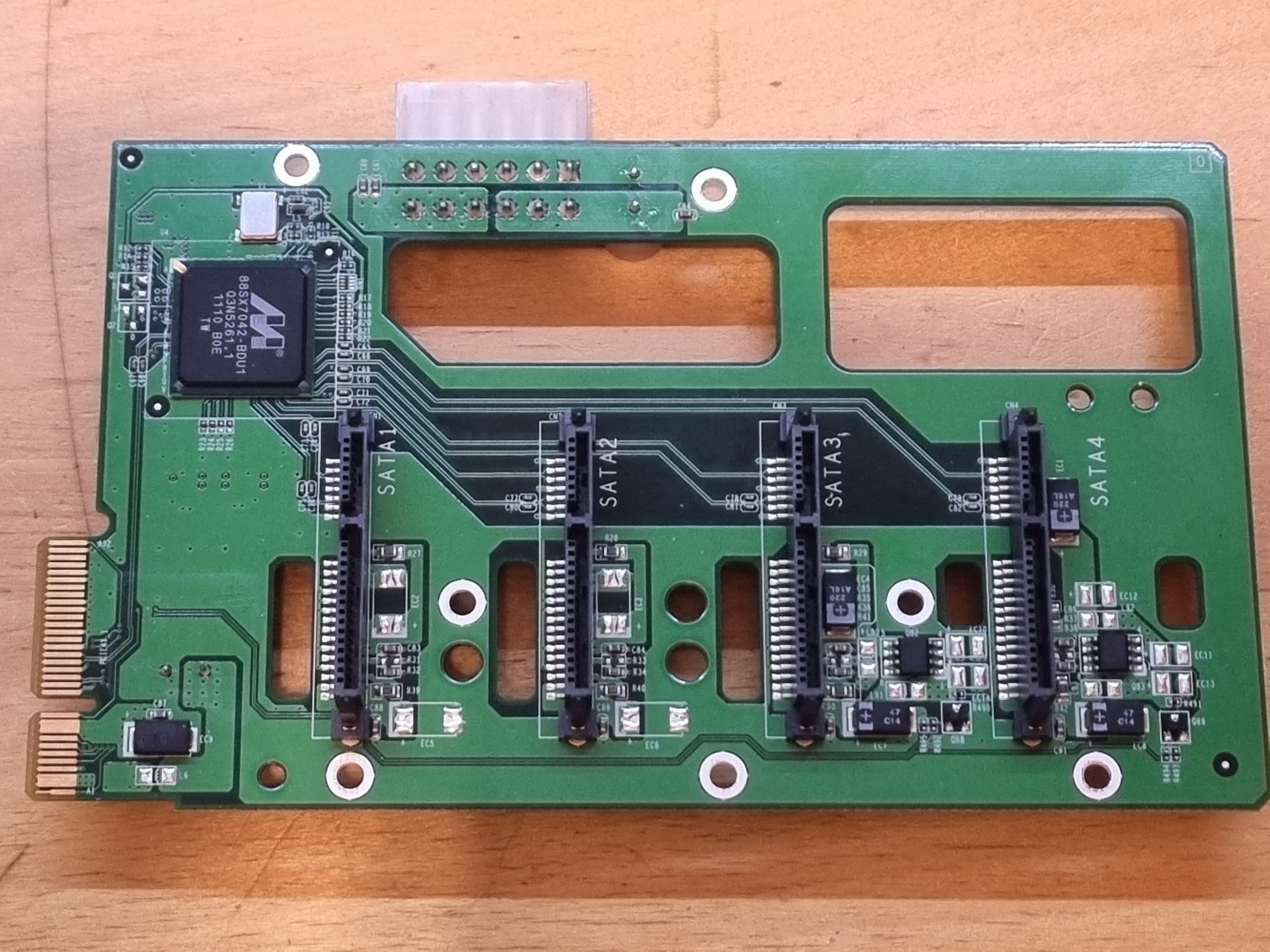
This got me thinking. The new Raspberry Pi 5 has a PCIe connector on it. I could potentially plug this backplane directly in to the Raspberry Pi 5 and run free open-source NAS software, rejuvenating my QNAPs to run up to date software, on modern hardware, economically, and undo their EOL status. I could continue to upgrade them in the future with new Raspberry Pi hardware, new software, giving them potentially decades more life. Very environmentally friendly, reducing e-waste and giving me handy additional storage, and a cool hardware project to tinker with at the weekends.
I called the project PiNAP, a portmanteau of “Pi” and “QNAP” 😊
PCIe Adapters
I searched for PCIe card slot adapters for the Raspberry Pi 5 and found a popular version on the PiHut website. I bought a SupTronics X1010 PCIe adapter. I also checked the Debian releases to see if they included the Marvell 88SX7042 drivers in the main kernel. I didn’t really want to have to compile a custom kernel. Lucky they are supported natively. So, this should be a simple plug and play project. (ominous foreshadowing)
When the adapter arrived, I was excited to try it out. I first tried it with no external power, booted the Pi5 and ran “lspci” and was disappointed to see no Marvel SATA adapter listed in the output. Thus began three weeks of tinkering and tearing my hair out trying to work out why the Pi5 wouldn’t recognise the PCIe SATA adapter. I will condense three weeks into two lines, but I tried every combination of dtparam in the boot.conf file, every variation of power to the card and drives, every variation of disks, with HDD and SSD and lots of Googling.
During this time, I was venting with my geeky friends on our WhatsApp group. My long time friend and Jedi level tinkerer Oli, also had a TS-412, and thought he’d try it our too. Within a single day his was working :-O. It would seem not all PCIe adapters are born equally. He bought a PCIe adapter made by 52PI (The Pi Hut – PCIe Slot for Raspberry Pi 5 (P02)) and it basically worked out of the box, with no disks or external power.
So, I bought one too, and behold, I had a working prototype (Thanks Oli)
$ lspci 0001:00:00.0 PCI bridge: Broadcom Inc. and subsidiaries BCM2712 PCIe Bridge (rev 21)--> 0001:01:00.0 SCSI storage controller: Marvell Technology Group Ltd. 88SX7042 PCIe 4-port SATA-II controller (rev 02) 0002:00:00.0 PCI bridge: Broadcom Inc. and subsidiaries BCM2712 PCIe Bridge (rev 21) 0002:01:00.0 Ethernet controller: Raspberry Pi Ltd RP1 PCIe 2.0 South Bridge
I was slightly disappointed that I could not fit the Pi5 and PCIe adapter directly on to the backplane in place of the old motherboard. This would have been perfect. But the PCIe adapter is round the wrong way to fit on the card, without hitting the case. I briefly considered designing my own motherboard that took a Raspberry Pi 5 compute module and had a PCIe connector in the right place, so the new board would fit directly on to the old mounting holes, but although I’ve designed and built many PCBs in my time, I’ve never made one with PCIe traces. That requires controlled impedance and more complex routing. Maybe if there is demand I’ll consider that in phase two.
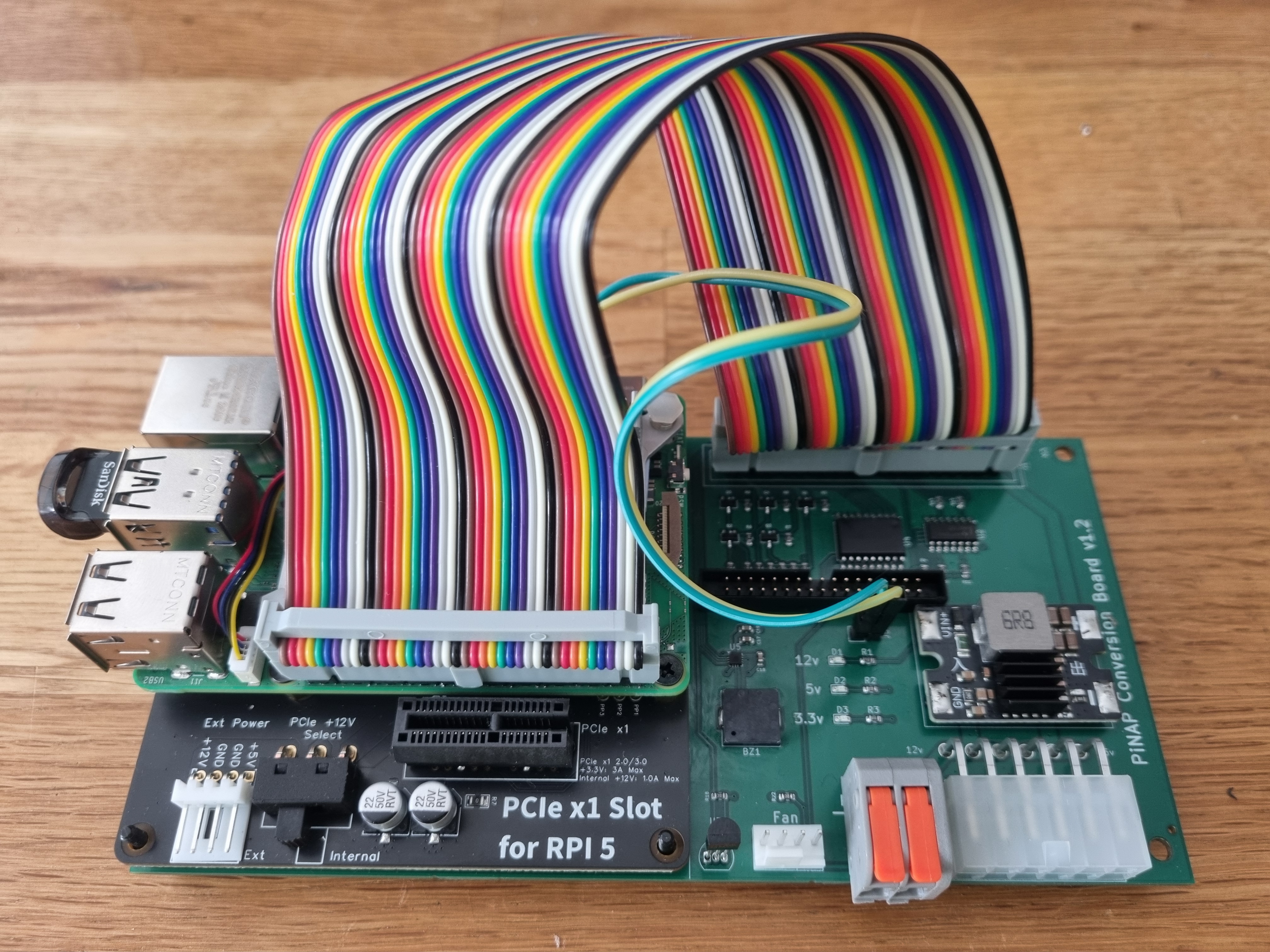
The QNAP case has a lot of spare room inside and there is ample space at the top to mount the Pi5 and adapter card, and I can run a PCI extension cable down to the backplane card. I also needed a high current 5v supply to power the hard disks and the Pi. The original QNAP power adapter is 120W 12v/10A which is enough to power everything, and I can reuse the existing power supply. I just need to add a reasonably large step-down converter to provide the 5v at 6-8A from the 12v supply to power the hard disks.
A typical 3.5” disk needs less than 1A for both 12v and 5v supplies. So, all four disks shouldn’t consumer more than 5v/4A and 12v/4A peak load.
The cooling fan is a PWM fan 4-pin fan, so the speed can be controlled with a PWM signal. I also added a temperature sensor in my design so I can speed up the fan if the interior of the case gets hot and slow it down as it cools to reduce noise.
Front Panel LED control
It would also be nice to get the original power switch and LEDs working on the front panel too, so the entire unit is more user friendly and functional. I traced the IO ribbon cable to reverse engineer the LED and switch board.

This LED Board has a very peculiar circuit and seems to mix 5v and 3.3v logic to power the LEDs. I’m sure this has something to do with reusing it on other QNAP models and in fact the motherboard has various ICs and regions unpopulated. I guess most of the hardware gets reused in lots of different models with a slightly different configuration, to reduce hardware designed time and variations.
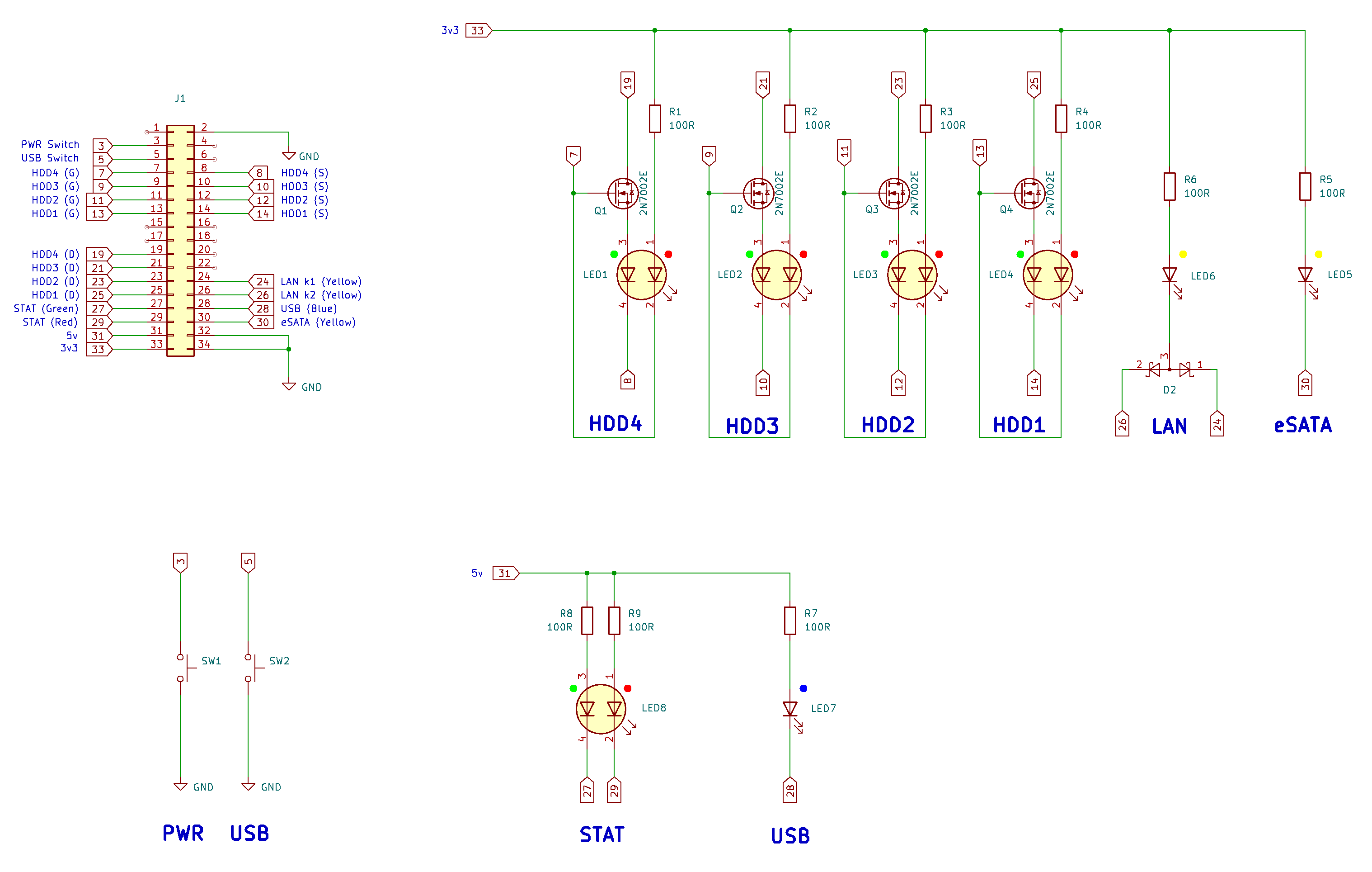
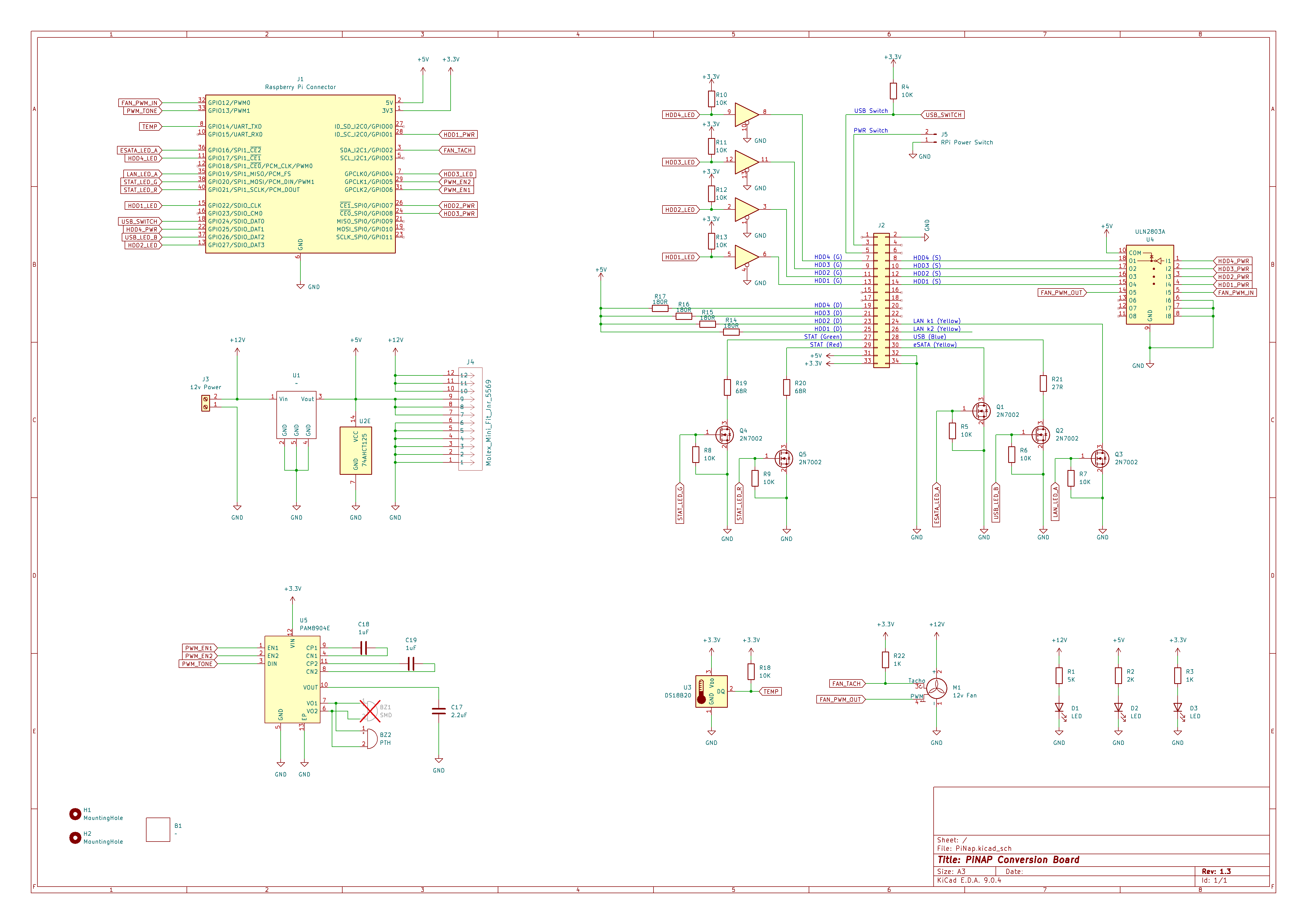
The Green hard disk LEDs are powered via 5v and the Red hard disk LEDs is powered by 3.3v, both are controlled by a single MOSFET, operated by the same GPIO signal, but they have different power sources.
The LAN and eSATA LEDs are powered from 3.3v and the Status and USB LEDs are powered by 5v. They are each controller via a MOSFET using the Pi5 GPIO.
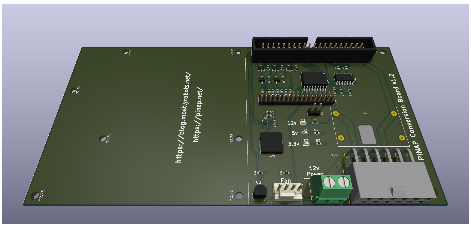
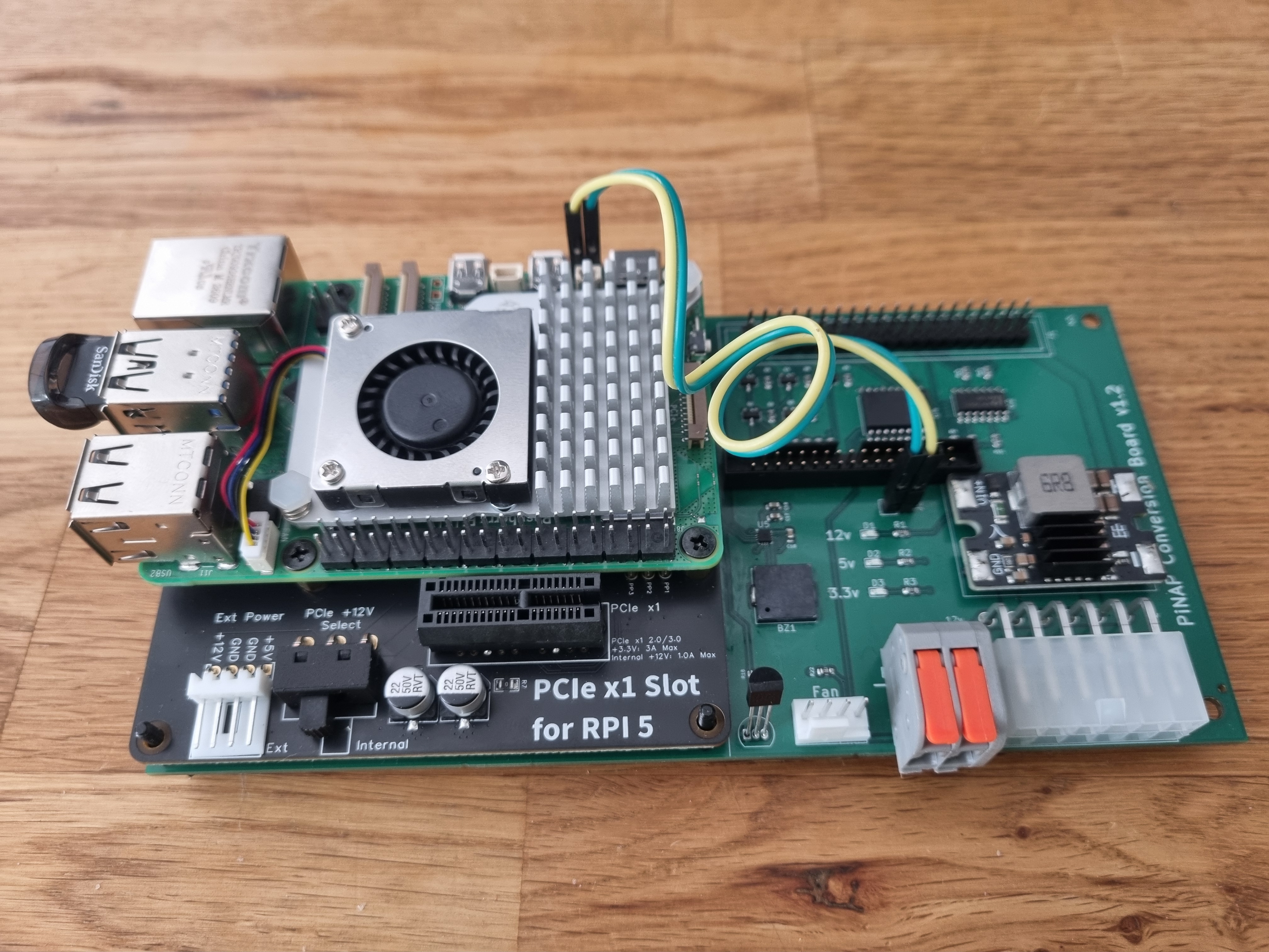
Seeing as I needed an external power circuit, fan connector and complex GPIO control of the LEDs, I designed a custom PCB mounting board to hold the Pi, PCIe connector board and provide the logic circuits and power connector. This would allow me to mount everything in one place, with tidy cable management and reuse of most of the internal cables and front panel. I added a piezo buzzer and amplifier, so the device could beep like the old QNAP on startup and shutdown and if there are errors. I managed to find all the right connectors on Digikey so I can reuse the original hard disk power cable, the front panel ribbon cable, and the power supply. I had these manufactured by JLCPCB and they arrive quickly.
LED Triggers
Connecting everything was relatively straight forward and the LEDs seem to work with the right combination of GPIOs enabled.
I can control the LEDs using a kernel Device Tree Overlay. However, only certain activities are supported in the stock Raspberry Pi kernel to trigger the LEDs.
You can list the available trigger modules by catting the trigger file:
$ sudo cat /sys/class/leds/disk1\:activity/trigger[none] default rc-feedback kbd-scrolllock kbd-numlock kbd-capslock kbd-kanalock kbd-shiftlock kbd-altgrlock kbd-ctrllock kbd-altlock kbd-shiftllock kbd-shiftrlock kbd-ctrlllock kbd-ctrlrlock timer oneshot heartbeat backlight cpu cpu0 cpu1 cpu2 cpu3 default-on input panic actpwr mmc1 mmc0 netdev rfkill-any rfkill-none rfkill0 rfkill1
I used the stock “heartbeat” trigger to flash the Status LED and the “netdev” trigger to flash the LAN LED to show ethernet activity.
However, there is no “sda”, “sdb”, etc, triggers in the stock kernel, so it’s not possible to automatically trigger the hard disk LEDs on disk activity. I wrote a small python daemon to monitor each hard disks activity and flash the hard disk LEDs accordingly, rather than compiling a custom kernel. This has a tiny overhead (less than 1% CPU) so even though it’s not ideal, it won’t impact performance.
The python daemon also monitors for USB button presses, and monitors the temperature sensor and adjusts the PWM fan speed accordingly.
Hardware Requirements
To convert your QNAP TS-412 to Raspberry Pi and Open Media Vault you will need the following hardware:
- Raspberry Pi 5 (I am using the version with 8GB RAM, but 2GB or 4GB will probably work perfectly well too)
- PCIe Slot for Raspberry Pi 5 (P02)
- PCIe Slot for Raspberry Pi 5 (P02)
- Some PCIe slots don’t work, so be careful to get this specific model, which I can confirm works with the SATA backplane.
- PCIe extension cable
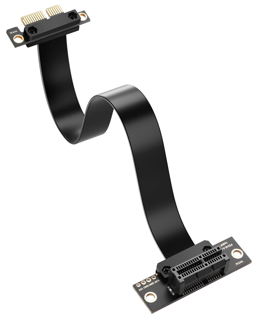
- PCIe 4.0 X1 90 Degree Extension Cable (30CM)
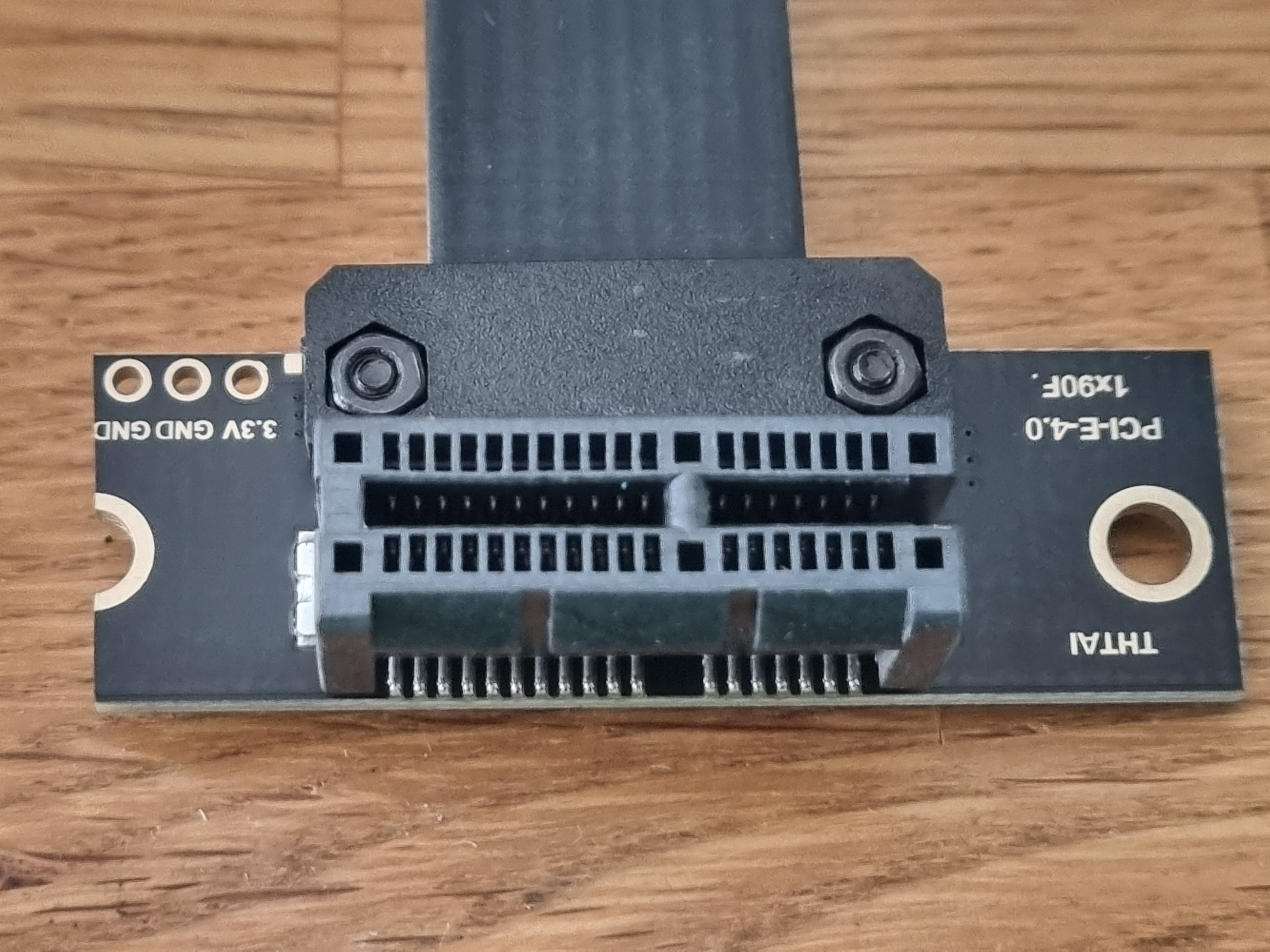
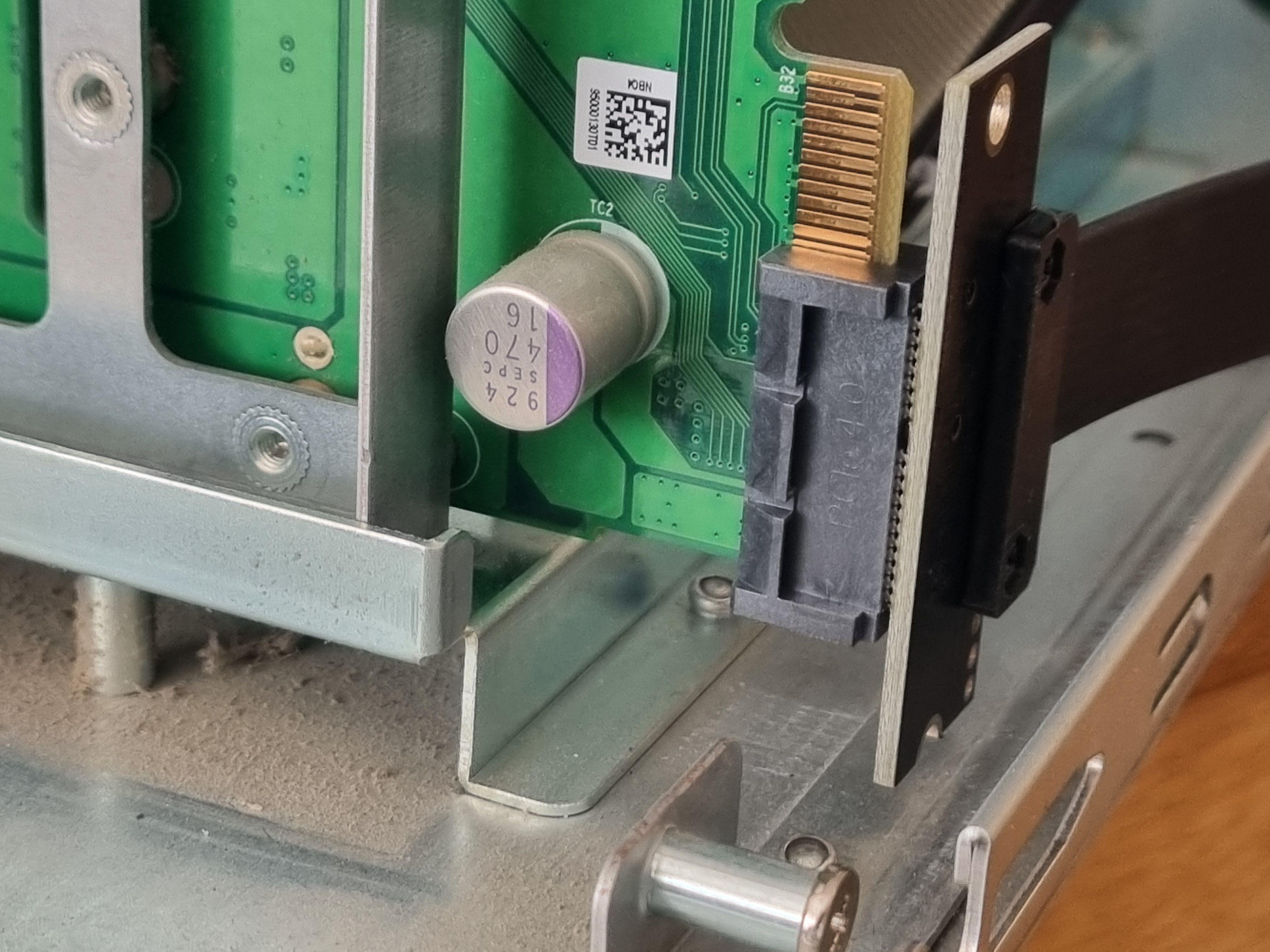
- Not all cables work correctly. This one specifically has the right angles in the correct orientation, however you will need to sand off 5 mm of the edge of the PCB to get it to fit. This doesn’t affect its functionality as long as the modification is clean.
- A PiNAP conversion kit (available from Tindie)
- This includes;
- the fully populated conversion PCB with 5v buck convertor.
- the power socket and bolts
- nylon PCB standoffs
- You will reuse your QNAP case, power supply and internal cables.
- You will need appropriate 3.5″ or 2.5″ hard disks.
- You will also need a Dremel to cut out a hole in the back of the case and drill and 2mm drill bit to mount the power socket.
- A soldering iron and steady hand to modify and solder a tiny wire on the SATA backplane to enable the SAT3 & SATA4 power.
PCIe extension cable
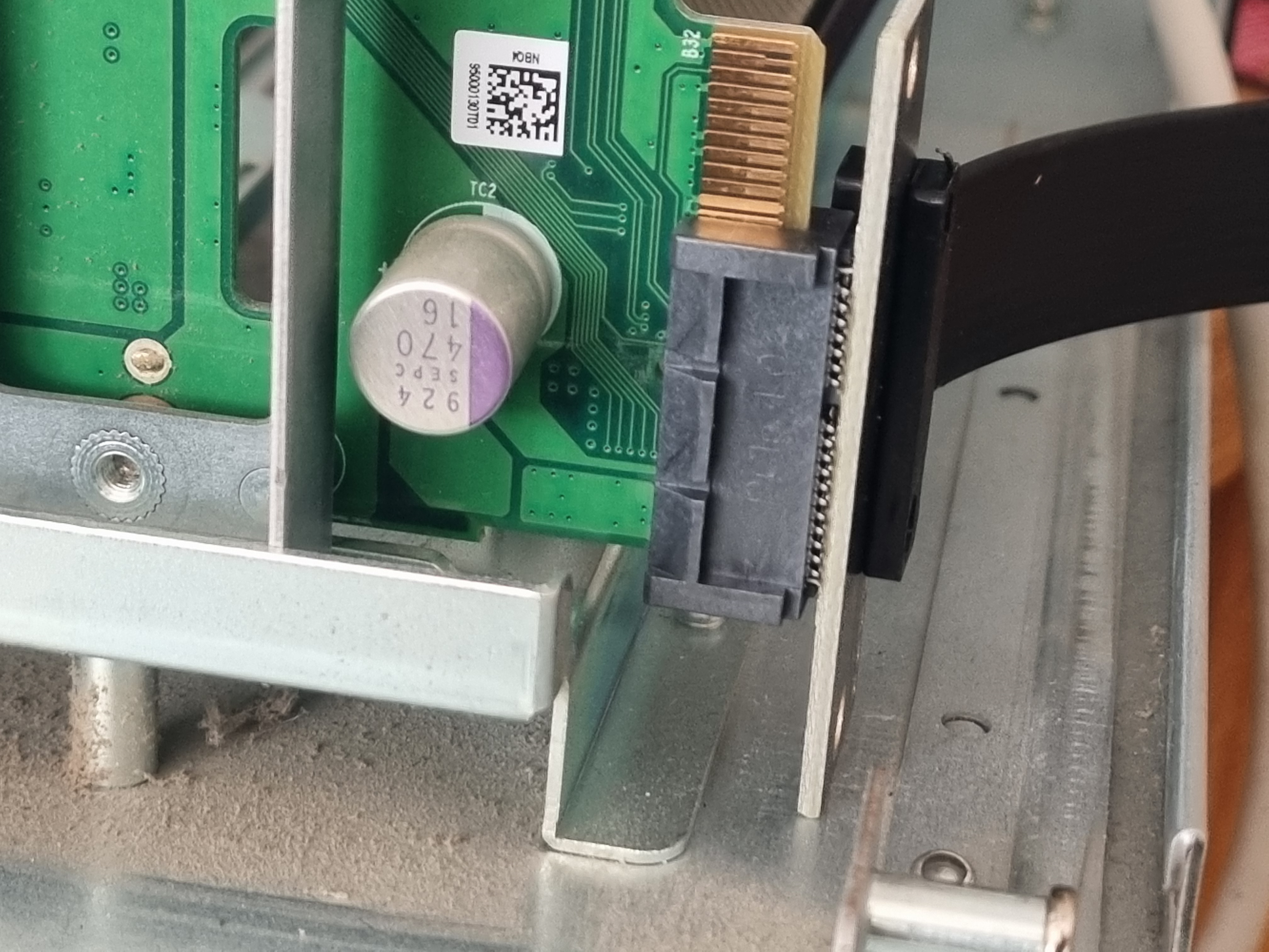
The PCIe backplane connector is very close to the bottom of the case. I struggled to find a PCIe extension cable that would fit, so I ended up modifying one. I sanded the edge of the PCB down to make it fit. Although this isn’t a recommended option, I couldn’t find an alternative, and double checked for short circuits before plugging it in.
Case Modification
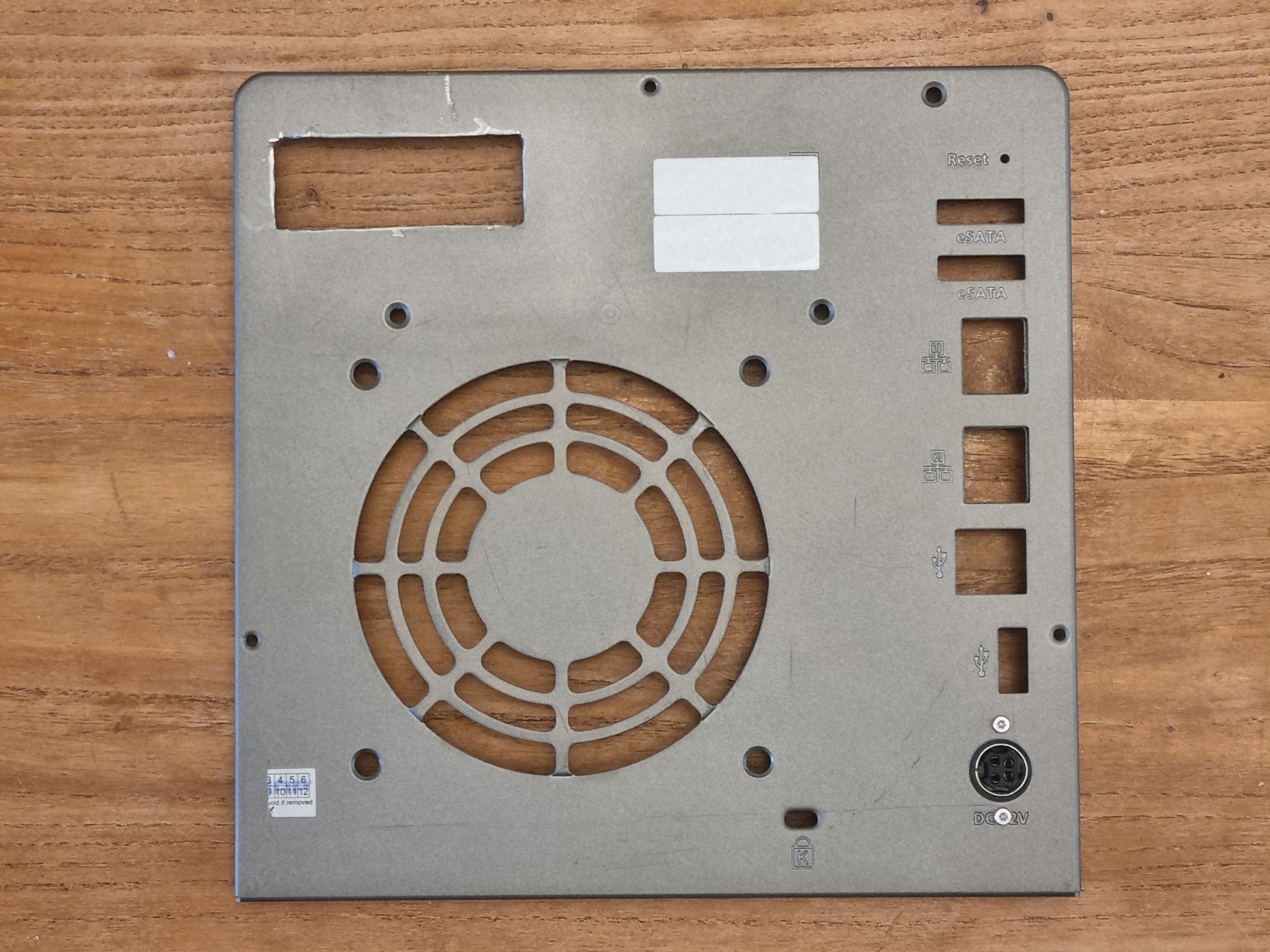
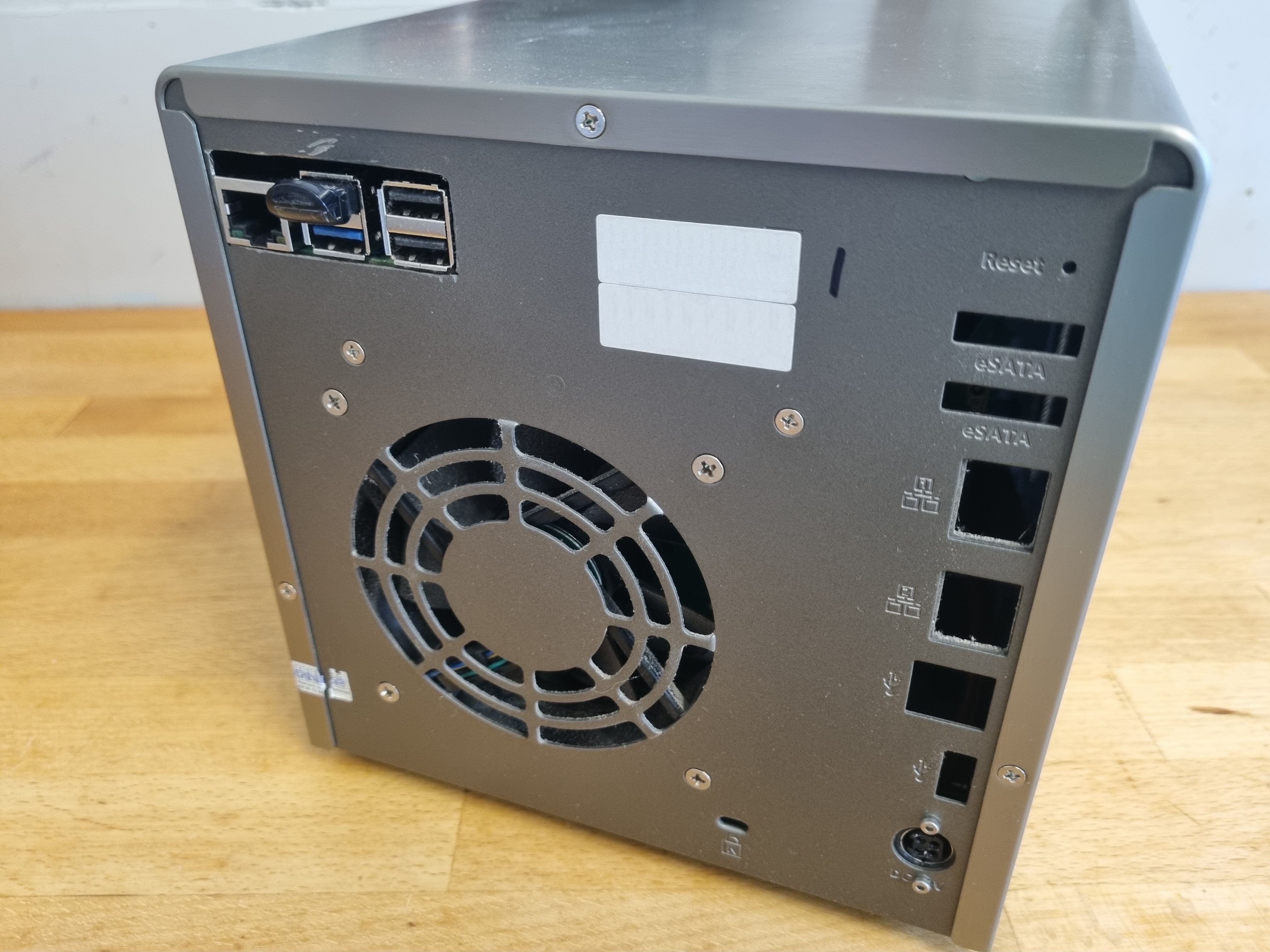
The only big modification was to cut a hole in the back of the QNAP case to get access to the Pi5 network and USB ports. Maybe one day I’ll design a 3D printed panel, but for now, I just cut a large square hole with a Dremel!
I also drilled two small 2mm holes to mount the power connector in its original hole as there is no longer a motherboard behind it.
SATA Backplane Power
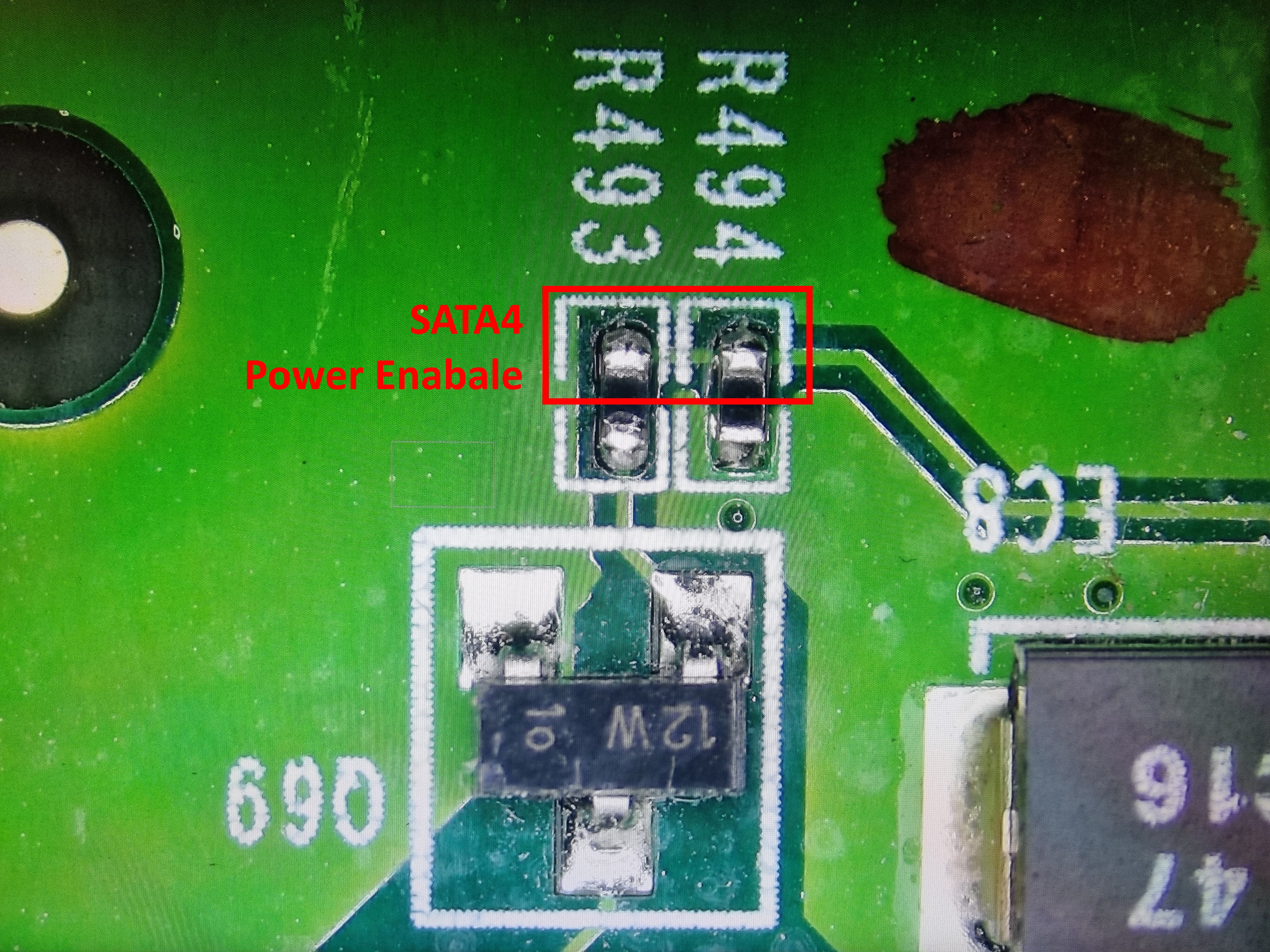
There is also another minor issue with the SATA backplane card. It uses two unused or reserved pins on the PCIe connector to control the power to the third and fourth hard disk connectors. I assume this is to limit the start up current and prevent all four hard drives spinning up at the same time. The custom motherboard uses these PCIe pins to stagger disks 3 and 4 to power up after a delay.
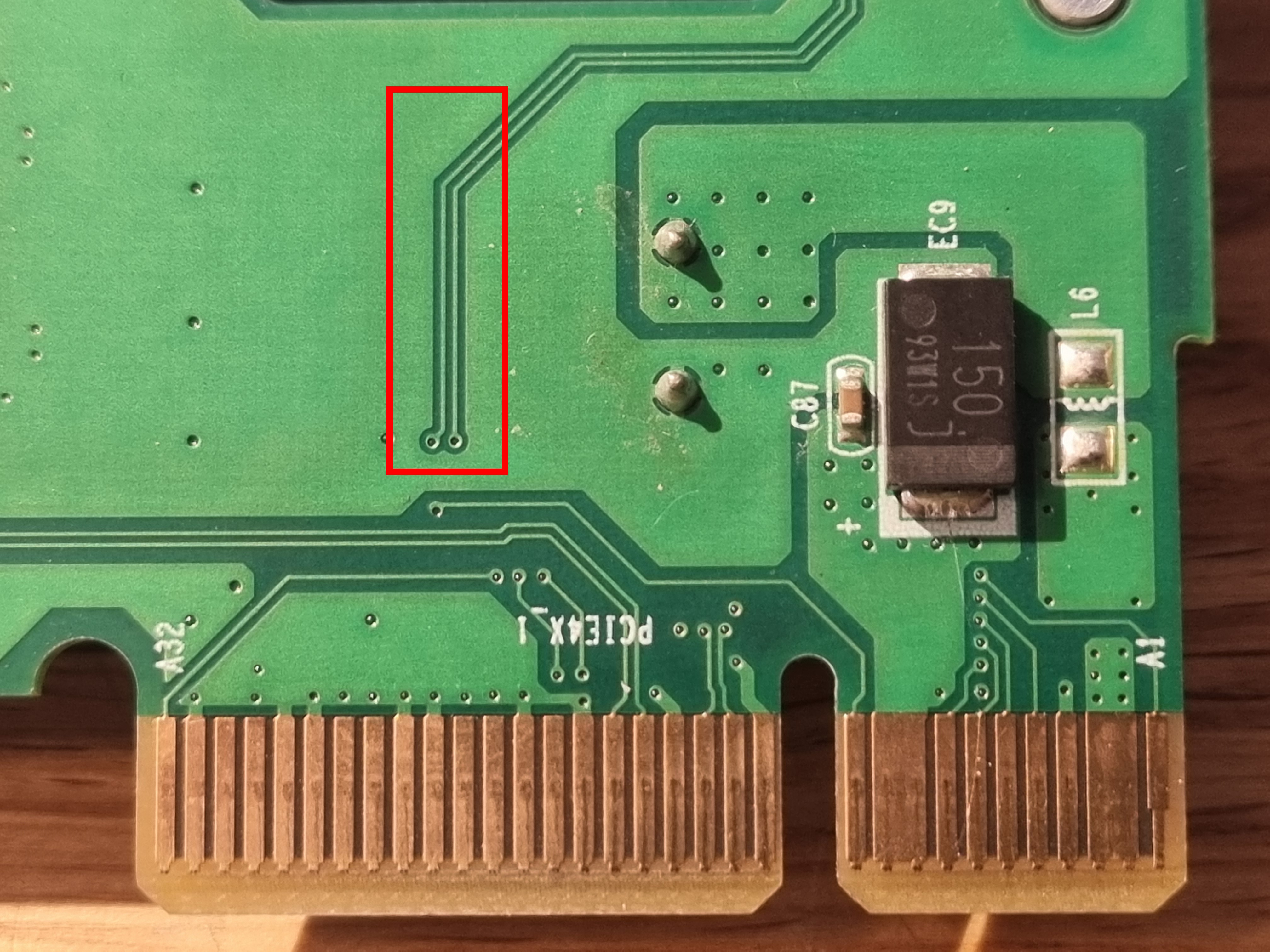
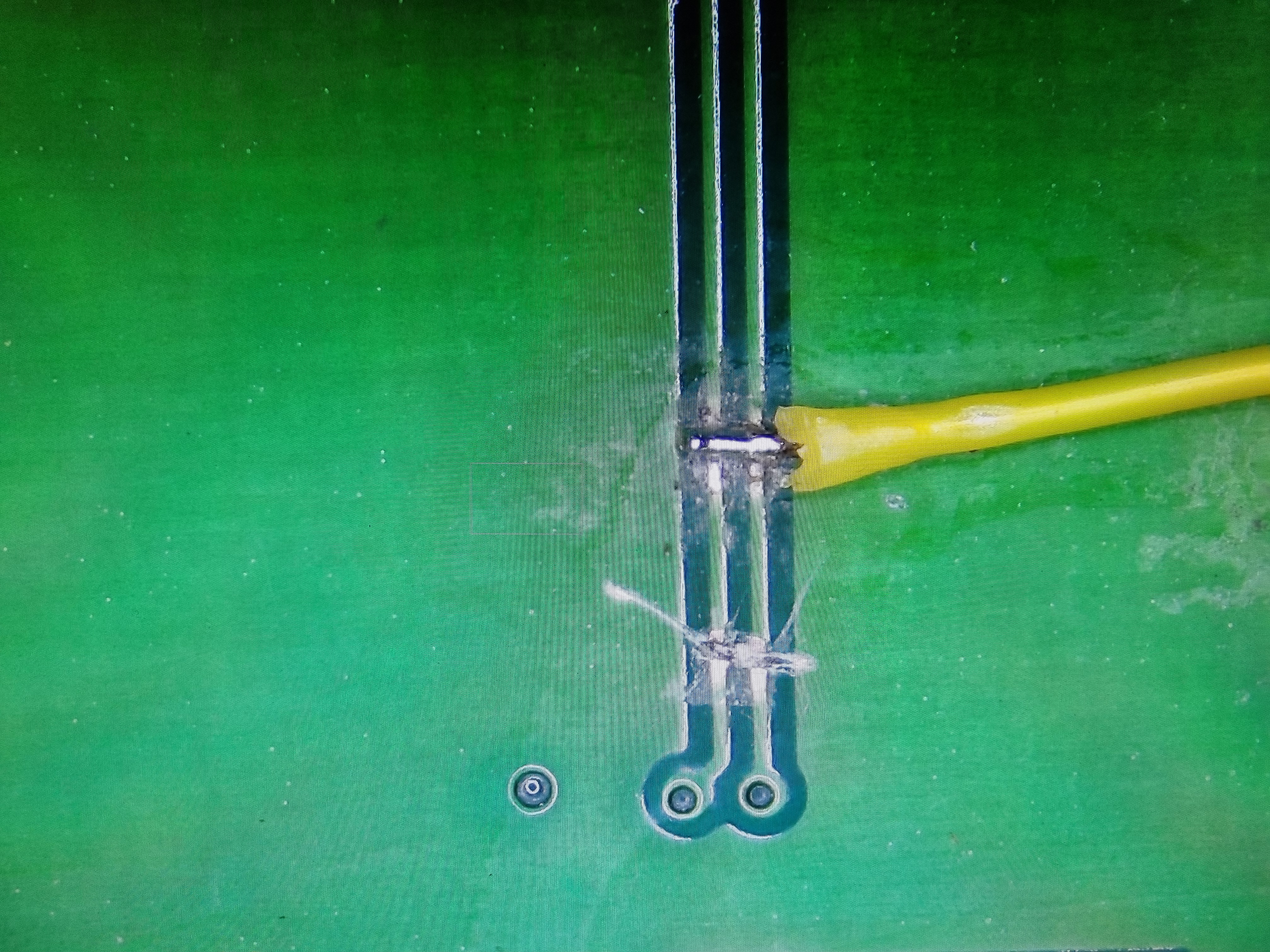
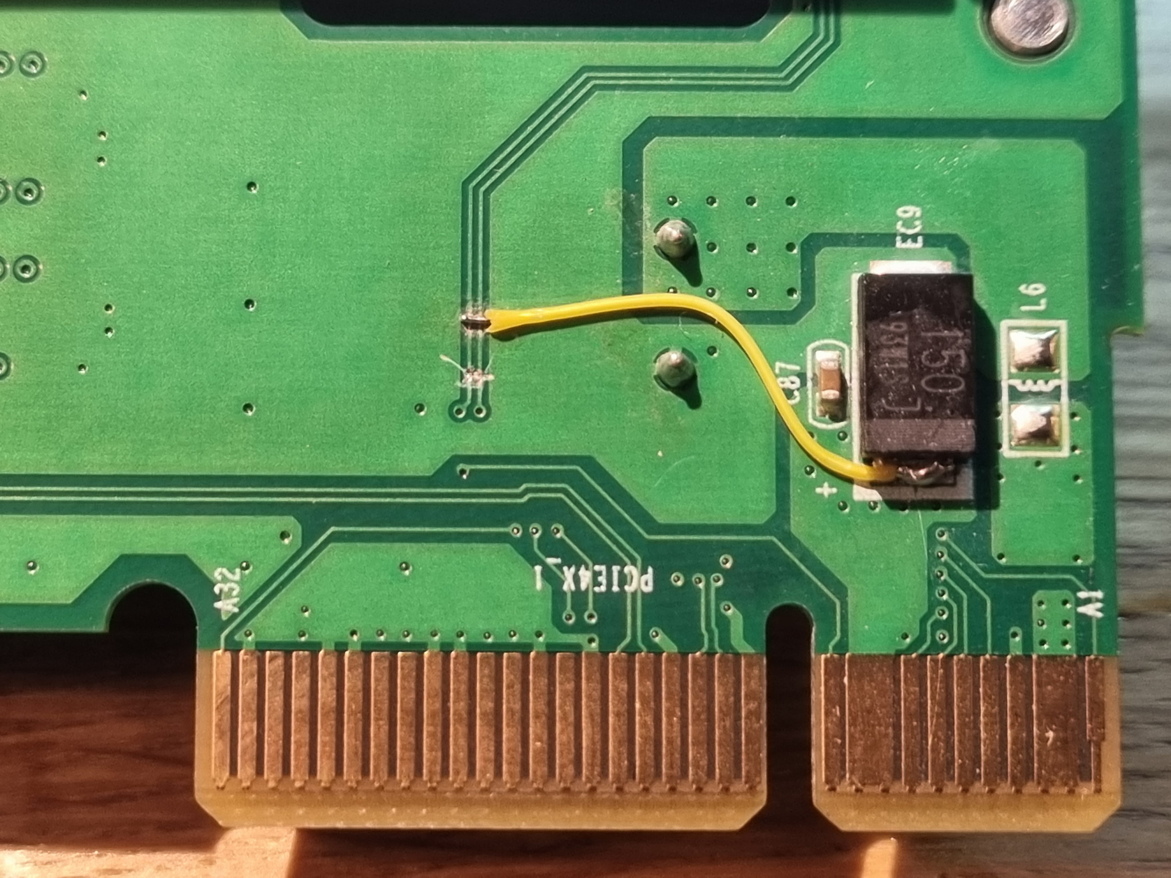
I couldn’t do this with the Pi5, without a custom motherboard. So, I opted to cut the traces on the backplane card that go to the PCIe connector and tie them permanently high to 3.3v. This would force all the drives to power up simultaneously, and generate large initial power draw, but we’ll see how it goes. In the future I could add a jumper wire, and perhaps route the power enable signals to a GPIO pin on the Pi5 if I do get issues with power surges, but if I use a big enough power supply it should be fine.
SATA3 power enable is on the outside pins of R492 & R495
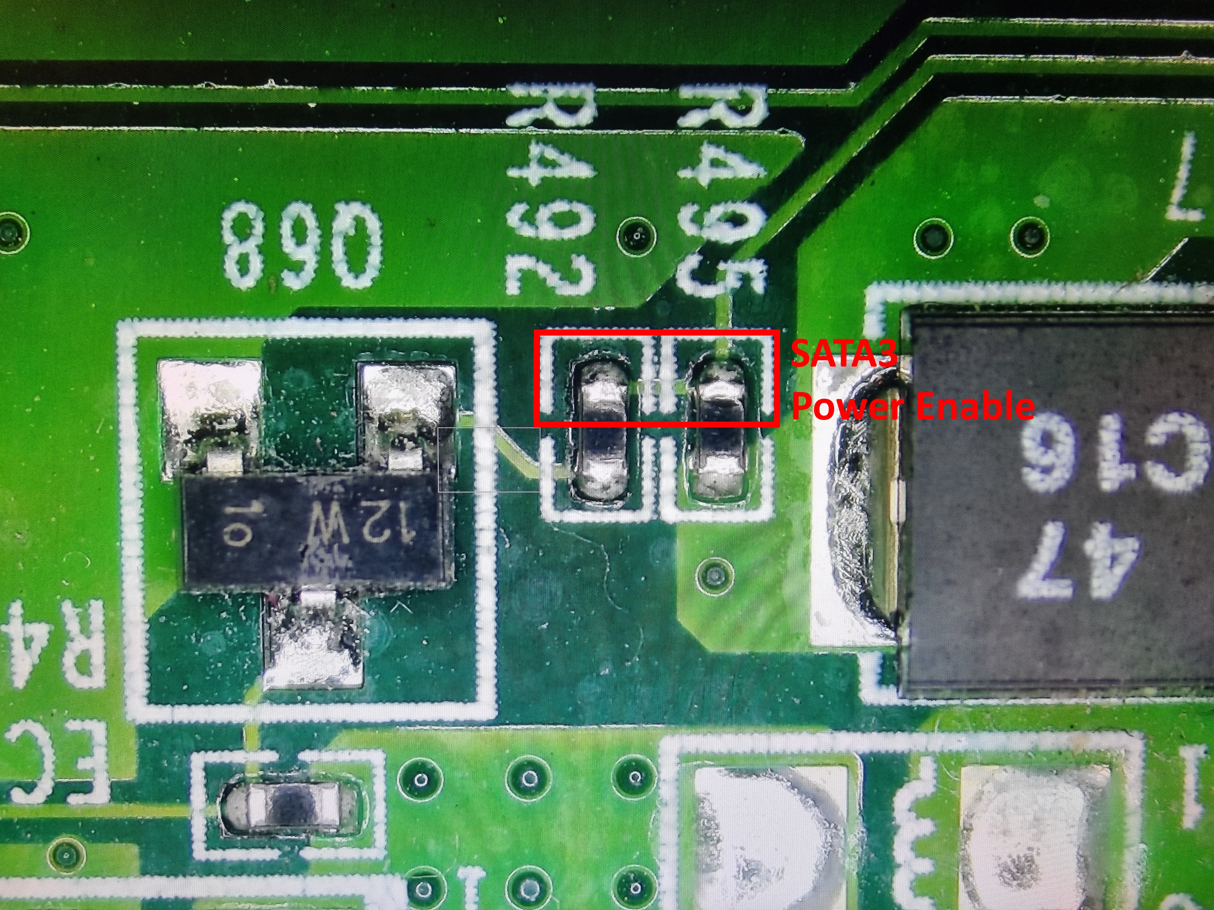
SATA4 power enable is on the outside pins of R493 & R494
Both traces run down the PCB to the PCIe connector, where I cut them, soldered a small wire to them and tied them to a 3.3v. I found a 3.3v source at the bottom of the card on the positive pin of “EC9”
Power Switch
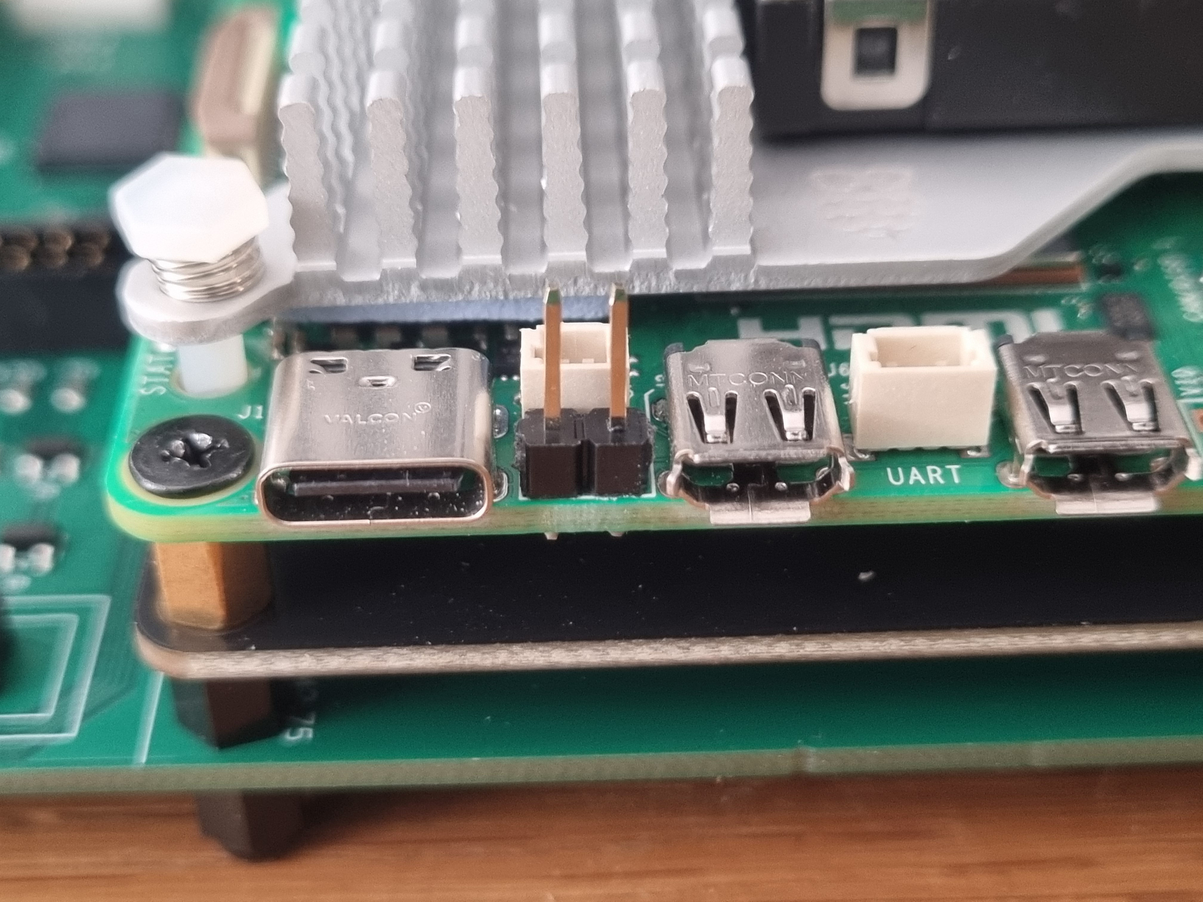
The front panel power switch is terminated on the conversation board with a two pin header. This can be connected to the Pi5 power switch header, to enable the Pi5 to be controlled by the front panel power switch. You will need to solder a two pin header on to the Raspberry Pi 5, then connect the jumper wire.
USB socket and switch
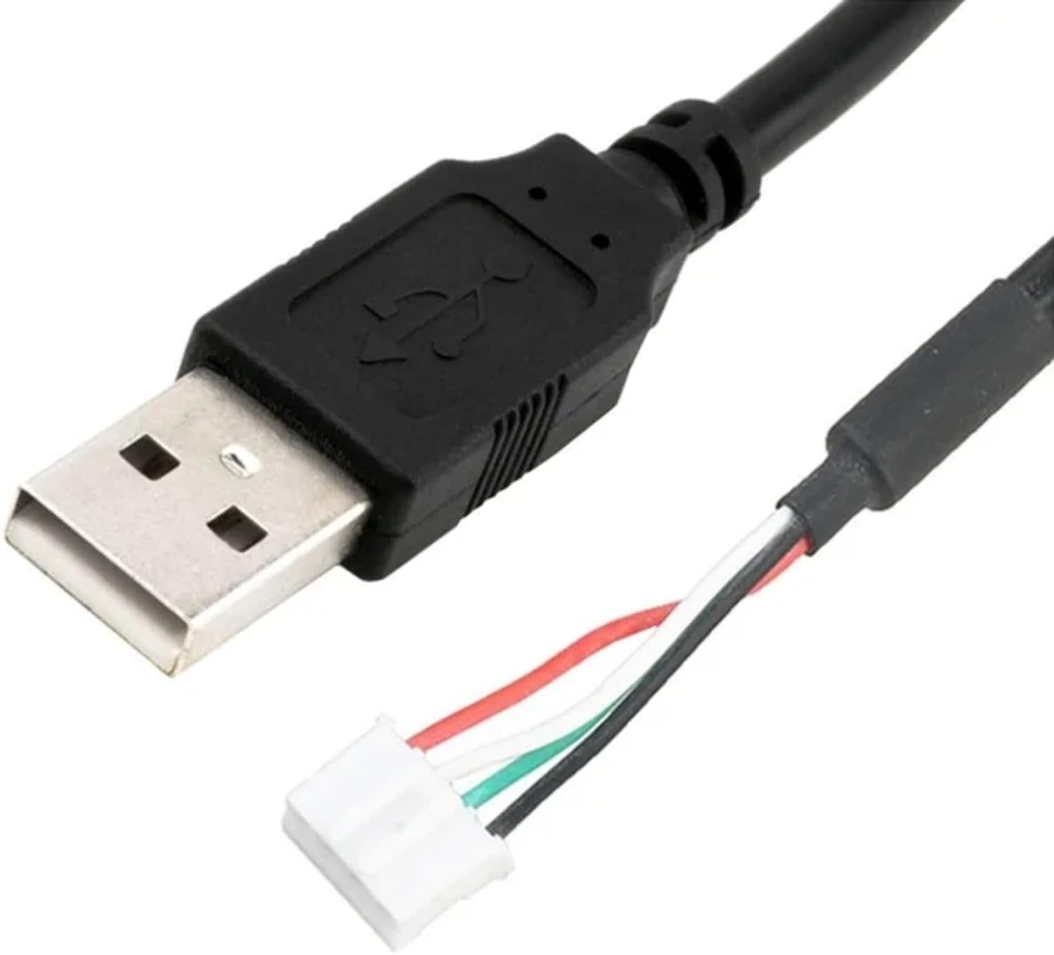
Currently I don’t have a need for the front panel USB socket or switch. The socket can be connected to one of the spare USB ports on the Pi5 with an extension cable. The front panel USB switch is connected to a GPIO, but current doesn’t do anything other than flash the USB LED when pressed (just to show its working). This could be configured at a later stage to trigger a copy script on the Pi5 to copy the contents of the USB disks to a folder in OMV. You can buy a USB lead with a 4 pin JST-PH connector, and route the cable out of the back of the case though one of the holes and plug it into the Pi 5.
Software Installation
Raspberry Pi OS Installation
Create a USB flash disk with the latest Raspberry Pi OS 64 bit Lite image using the Raspberry Pi Imager software. Open Media Vault only works on the Lite version of the OS.
The Raspberry Pi 5 will not initially boot when installed in the PiNAP board because it cannot measure the power supply and refuses to boot from USB. You need to make a change to the /boot/firmware/config.txt. There are two options to achieve this:
Option 1 – Boot the Pi5 initially with USB-C Power
Before installing the Pi5 in the PiNAP board you can boot the Pi5 independently, install the Raspberry Pi OS and make some changes to the /boot/firmware/config.txt. Boot the Pi 5 from the USB flash disk with a compatible 5v USB-C supply and once it has booted, edit the /boot/firmware/config.txt file. Add the following lines to the end of the file:
usb_max_current_enable=1dtparam=pciex1dtoverlay=pwm,pin=12,func=4dtoverlay=w1-gpio,gpiopin=14
Save and shutdown.
You can now install the Pi5 in the PiNAP convertor PCB and connect all the connectors in the case and continue the installation process.
Connect the Pi 5 to the network and ensure everything is up to date:
sudo apt updatesudo apt upgrade
Reboot the Pi 5
Option 2 – Edit the config.txt file on the USB flash disk before installing
When you have created the USB flash disk with the latest Raspberry Pi OS 64 bit Lite image using the Raspberry Pi Imager software, insert the flash disk into a suitable laptop or computer. In the “bootfs” partition you should find the file /config.txt. Add the following lines to the end of the file:
usb_max_current_enable=1dtparam=pciex1dtoverlay=pwm,pin=12,func=4dtoverlay=w1-gpio,gpiopin=14
Save the file and eject the USB flash drive.
You can now install the Pi5 in the PiNAP convertor PCB and connect all the connectors in the case and continue the installation process.
Connect the Pi 5 to the network and ensure everything is up to date:
sudo apt updatesudo apt upgrade
Reboot the Pi 5
Verify PCIe SATA Backplane is recognised
$ lspci 0001:00:00.0 PCI bridge: Broadcom Inc. and subsidiaries BCM2712 PCIe Bridge (rev 21)--> 0001:01:00.0 SCSI storage controller: Marvell Technology Group Ltd. 88SX7042 PCIe 4-port SATA-II controller (rev 02) 0002:00:00.0 PCI bridge: Broadcom Inc. and subsidiaries BCM2712 PCIe Bridge (rev 21) 0002:01:00.0 Ethernet controller: Raspberry Pi Ltd RP1 PCIe 2.0 South Bridge
Open Media Vault Installation
I installed Open Media Vault (OMV) first and get that running, then install the Device Tree Overlay and daemon. OMV configured the ethernet port as “end0” not the default “eth0” so the device tree needs to reflect that.
The Open Media Vault install was very straight forward. The instructions are easy to follow. Follow the instructions for Raspberry Pi: https://github.com/OpenMediaVault-Plugin-Developers/installScript
wget -O - https://github.com/OpenMediaVault-Plugin-Developers/installScript/raw/master/install | sudo bash
This should install Open Media Vault, you can then access the web interface using a browser.
Ensure everything is up to date:
sudo apt updatesudo apt upgrade
You can now setup Open Media Vault, install the various plugins you need, configure the disks and RAID Arrays and create a filing system and shares.
$ lsblkNAME MAJ:MIN RM SIZE RO TYPE MOUNTPOINTSsda 8:0 1 28.7G 0 disk ├─sda1 8:1 1 512M 0 part /boot/firmware└─sda2 8:2 1 28.2G 0 part /sdb 8:16 0 2.7T 0 disk └─md0 9:0 0 8.2T 0 raid5 /export/data /srv/dev-disk-by-uuid-abcdef12-39fd-456a-abcd-123456789123sdc 8:32 0 2.7T 0 disk └─md0 9:0 0 8.2T 0 raid5 /export/data /srv/dev-disk-by-uuid-abcdef12-39fd-456a-abcd-123456789123sdd 8:48 0 2.7T 0 disk └─md0 9:0 0 8.2T 0 raid5 /export/data /srv/dev-disk-by-uuid-abcdef12-39fd-456a-abcd-123456789123sde 8:64 0 2.7T 0 disk └─md0 9:0 0 8.2T 0 raid5 /export/data /srv/dev-disk-by-uuid-abcdef12-39fd-456a-abcd-123456789123
Reboot the Pi 5
PiNAP Software Installation
cd ~git clone https://github.com/JonRussell00/PiNAP.gitcd PiNAPsudo cp pinap-leds.dts /boot/firmware/overlays/pinap-leds.dtssudo cp pinap-daemon.py /usr/local/bin/pinap-daemon.pysudo cp pinap-daemon.service /etc/systemd/system/pinap-daemon.servicesudo cp pinap-lan-led-trigger.service /etc/systemd/system/pinap-lan-led-trigger.servicesudo chmod +x /usr/local/bin/pinap-daemon.py
Configure OneWire for the Temperature Sensor
lsmod | grep w1
You should see w1_gpio and w1_therm listed. If not, load them:
sudo modprobe w1_gpiosudo modprobe w1_therm
Reboot the Pi 5
You should now be able to see the onboard OneWire temperature sensor:
$ sudo ls -la /sys/bus/w1/devices/lrwxrwxrwx 1 root root 0 Jun 18 01:39 28-00000xxxxxxx -> ../../../devices/w1_bus_master1/28-00000xxxxxxxlrwxrwxrwx 1 root root 0 Jun 18 17:12 w1_bus_master1 -> ../../../devices/w1_bus_master1
Make a note of the number of your temperature sensors unique number starting “28-“
Test the sensor reads the correct temperature substituting your unique ID in the following command:
$ sudo cat /sys/bus/w1/devices/28-000000000000/temperature | awk '{printf "%.2f\n", $1/1000}'28.75
Edit the daemon Python file /usr/local/bin/pinap-daemon.py and add your unique ID. Edit the TEMP_SENSOR_ID variable here:
# ---------------------------------------------------------------------------# Temperature sensor configuration (1-wire DS18B20 on GPIO 14)# ---------------------------------------------------------------------------# 1-wire device ID for the temperature sensor# ## UPDATE FOR YOUR SENSOR ID ##TEMP_SENSOR_ID = '28-000000000000'# Path to the sensor's temperature attribute (value is in milli-degrees C)TEMP_SENSOR_PATH = Path(f'/sys/bus/w1/devices/{TEMP_SENSOR_ID}/temperature')
Device Tree Overlay
Build the device tree overlay:
sudo dtc -@ -I dts -O dtb -o /boot/firmware/overlays/pinap-leds.dtbo /boot/firmware/overlays/pinap-leds.dts
Edit the /boot/firmware/config.txt file. Add the following lines to the end of the file:
dtoverlay=pinap-leds
Enable the netdev LED trigger
sudo modprobe ledtrig-netdevecho "ledtrig-netdev" | sudo tee -a /etc/modules
Double check your ethernet port is labelled “end0”.
$ ip link show1: lo: <LOOPBACK,UP,LOWER_UP> mtu 65536 qdisc noqueue state UNKNOWN mode DEFAULT group default qlen 1000 link/loopback 00:00:00:00:00:00 brd 00:00:00:00:00:002: end0: <BROADCAST,MULTICAST,UP,LOWER_UP> mtu 1500 qdisc fq_codel state UP mode DEFAULT group default qlen 1000 link/ether d8:3a:dd:ff:ff:ff brd ff:ff:ff:ff:ff:ff altname enxd83addffffff
if its still “eth0” you will need to change it to “end0” with:
sudo omv-firstaid
The LAN LED Trigger service assumes “end0”
Enable the Python Daemon
sudo systemctl daemon-reloadsudo systemctl enable pinap-daemon.servicesudo systemctl start pinap-daemon.service
Enable LAN LED Trigger Service
sudo systemctl daemon-reloadsudo systemctl enable pinap-lan-led-trigger.servicesudo systemctl start pinap-lan-led-trigger.service
Testing
At the end of the install process you should have the following lines at the end of your /boot/firmware/config.txt
usb_max_current_enable=1dtparam=pciex1dtoverlay=pinap-ledsdtoverlay=w1-gpio,gpiopin=14dtoverlay=pwm,pin=12,func=4
Reboot the Pi 5
All the features should now be functional:
- The Green Status LED on the front panel should make a heartbeat flashing pattern
- The Amber LAN LED should flash in time with network activity
- The four Green HDD LEDs should flash in time with disk activity
- If you press the USB button on the front panel, the Blue USB LED should light and the PiNAP should beep. I currently don’t use the USB button, USB LED or eSATA LED for anything. They are there for future expansion and compatibility. There’s no reason why you can trigger a script when the USB button is pressed to copy files from the USB to the RAID Array if you need that functionality.
- When you shutdown or startup the PiNAP should beep, in a similar fashion to the QNAP functionality.
⚠️ Important Safety Notes
- Always disconnect power before working with hardware.
- The SATA backplane modification requires precision soldering. Ensure you know what you are doing to avoid damaging the Raspberry Pi.
- Test all connections before closing the case.
Troubleshooting
- Pi won’t boot from PiNAP power: Ensure
usb_max_current_enable=1is set in config.txt - LAN LED not working: Verify ethernet interface is named “end0” using
ip link show - Temperature sensor not detected: Check w1_gpio and w1_therm modules are loaded
Performance
I tested the disk performance using iperf3 on the PiNAP. I did a test from one PiNAP to the other, on a gigabit wired network, configuring the server end to store data on the raid array. I can swamp my gigabit network connection during the transfer, which is good enough for me.
pi@pinap01:~ $ iperf3 -s -F /srv/dev-disk-by-uuid-abcdef12-39fd-456a-abcd-123456789123/data/iperffile-----------------------------------------------------------Server listening on 5201 (test #1)-----------------------------------------------------------Accepted connection from 10.1.0.182, port 38638[ 5] local 10.1.0.181 port 5201 connected to 10.1.0.182 port 38650[ ID] Interval Transfer Bitrate[ 5] 0.00-1.00 sec 111 MBytes 931 Mbits/sec [ 5] 1.00-2.00 sec 111 MBytes 934 Mbits/sec [ 5] 2.00-3.00 sec 111 MBytes 932 Mbits/sec [ 5] 3.00-4.00 sec 111 MBytes 934 Mbits/sec [ 5] 4.00-5.00 sec 109 MBytes 912 Mbits/sec [ 5] 5.00-6.00 sec 110 MBytes 927 Mbits/sec [ 5] 6.00-7.00 sec 111 MBytes 932 Mbits/sec [ 5] 7.00-8.00 sec 111 MBytes 934 Mbits/sec [ 5] 8.00-9.00 sec 111 MBytes 932 Mbits/sec [ 5] 9.00-10.00 sec 109 MBytes 918 Mbits/sec - - - - - - - - - - - - - - - - - - - - - - - - -[ ID] Interval Transfer Bitrate Sent 1.08 GByte / 1.08 GByte (100%) of /srv/dev-disk-by-uuid-abcdef12-39fd-456a-abcd-123456789123/data/iperffile[ 5] 0.00-10.00 sec 1.08 GBytes 929 Mbits/sec receiverpi@pinap02:~ $ iperf3 -c pinap01.woodsideConnecting to host pinap01.woodside, port 5201[ 5] local 10.1.0.182 port 38650 connected to 10.1.0.181 port 5201[ ID] Interval Transfer Bitrate Retr Cwnd[ 5] 0.00-1.00 sec 115 MBytes 963 Mbits/sec 0 761 KBytes [ 5] 1.00-2.00 sec 111 MBytes 929 Mbits/sec 0 1.04 MBytes [ 5] 2.00-3.00 sec 111 MBytes 929 Mbits/sec 143 872 KBytes [ 5] 3.00-4.00 sec 112 MBytes 941 Mbits/sec 143 727 KBytes [ 5] 4.00-5.00 sec 108 MBytes 906 Mbits/sec 0 834 KBytes [ 5] 5.00-6.00 sec 111 MBytes 934 Mbits/sec 0 836 KBytes [ 5] 6.00-7.00 sec 111 MBytes 931 Mbits/sec 0 837 KBytes [ 5] 7.00-8.00 sec 111 MBytes 929 Mbits/sec 0 898 KBytes [ 5] 8.00-9.00 sec 111 MBytes 931 Mbits/sec 143 725 KBytes [ 5] 9.00-10.00 sec 109 MBytes 917 Mbits/sec 0 834 KBytes - - - - - - - - - - - - - - - - - - - - - - - - -[ ID] Interval Transfer Bitrate Retr[ 5] 0.00-10.00 sec 1.08 GBytes 931 Mbits/sec 429 sender[ 5] 0.00-10.00 sec 1.08 GBytes 929 Mbits/sec receiveriperf Done.
Summary
I have had my PiNAP conversations running for over a month now, without any issues. One has 4 x 3TB disks, giving about 8 TB RAID5 filesystem, the second has 4 x 4TB disks, giving about 11TB RAID5 filesystem.
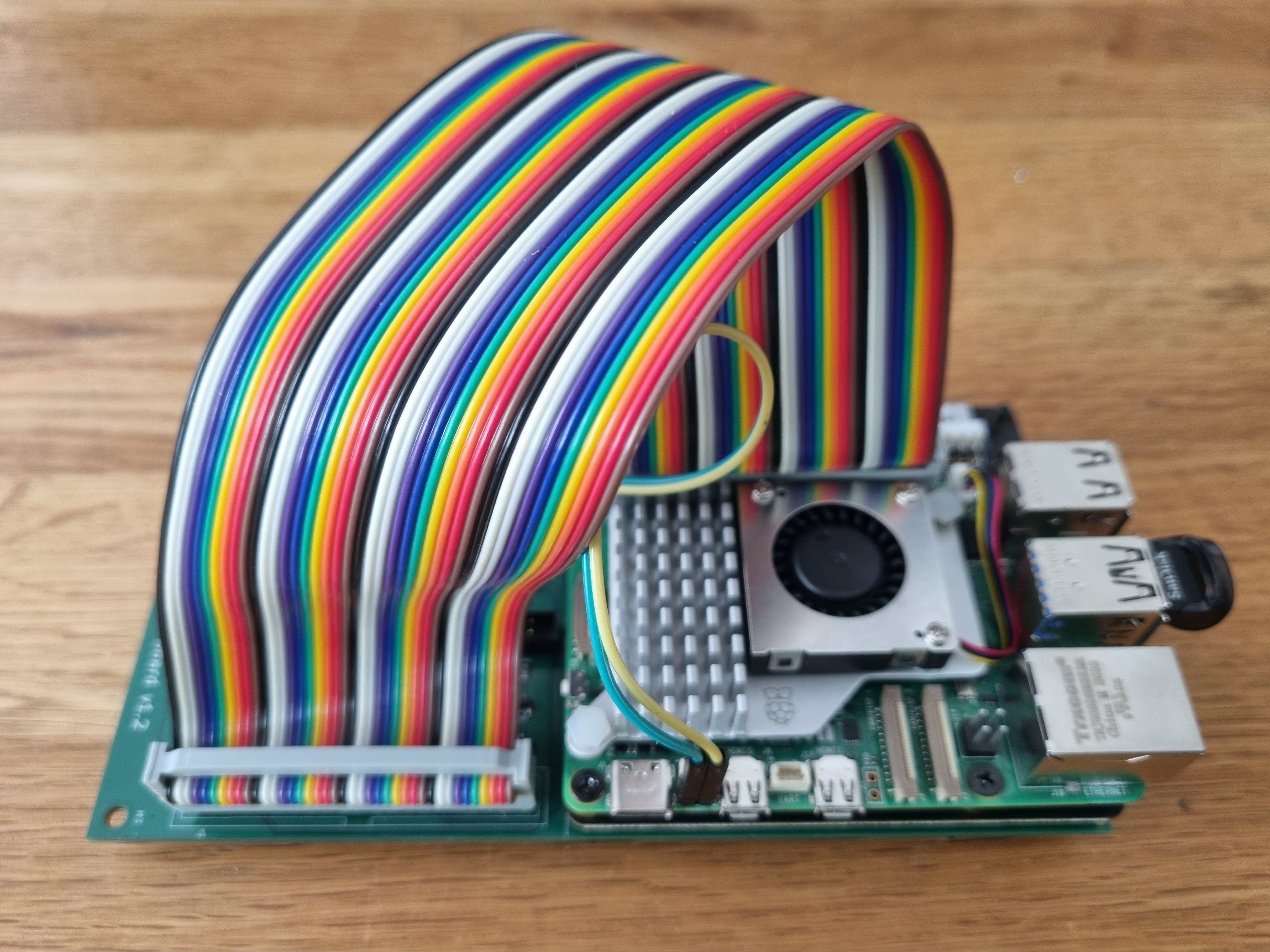
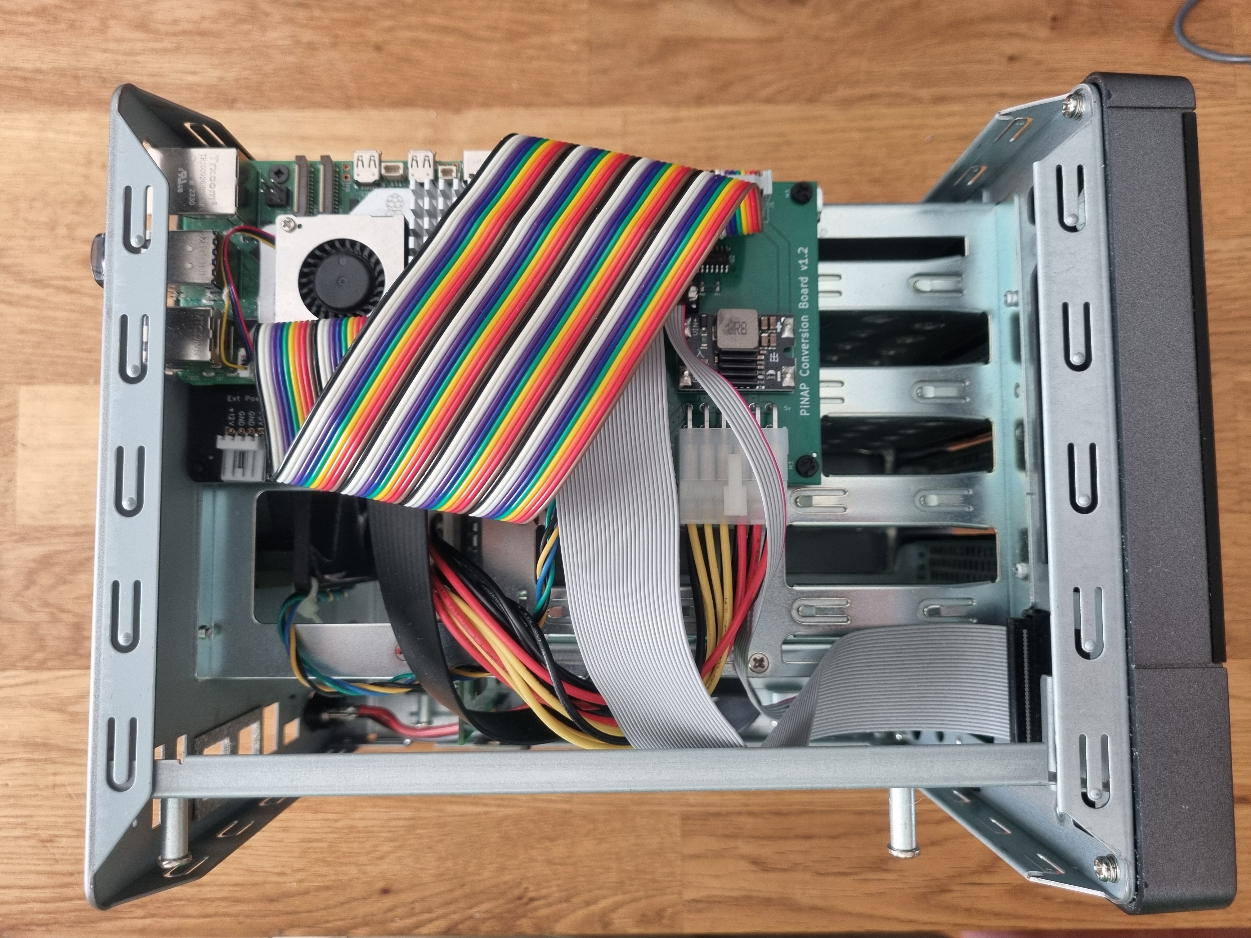
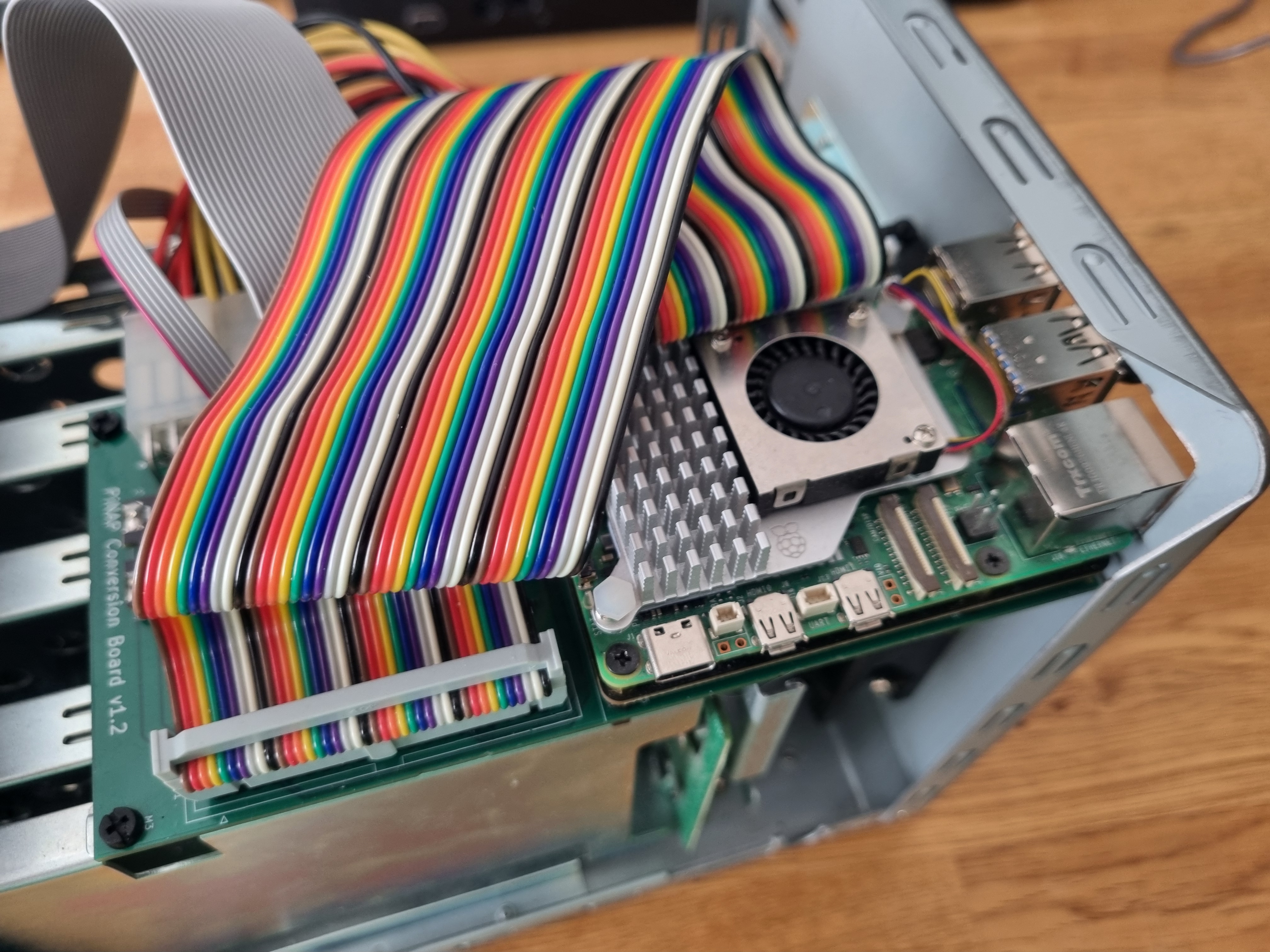
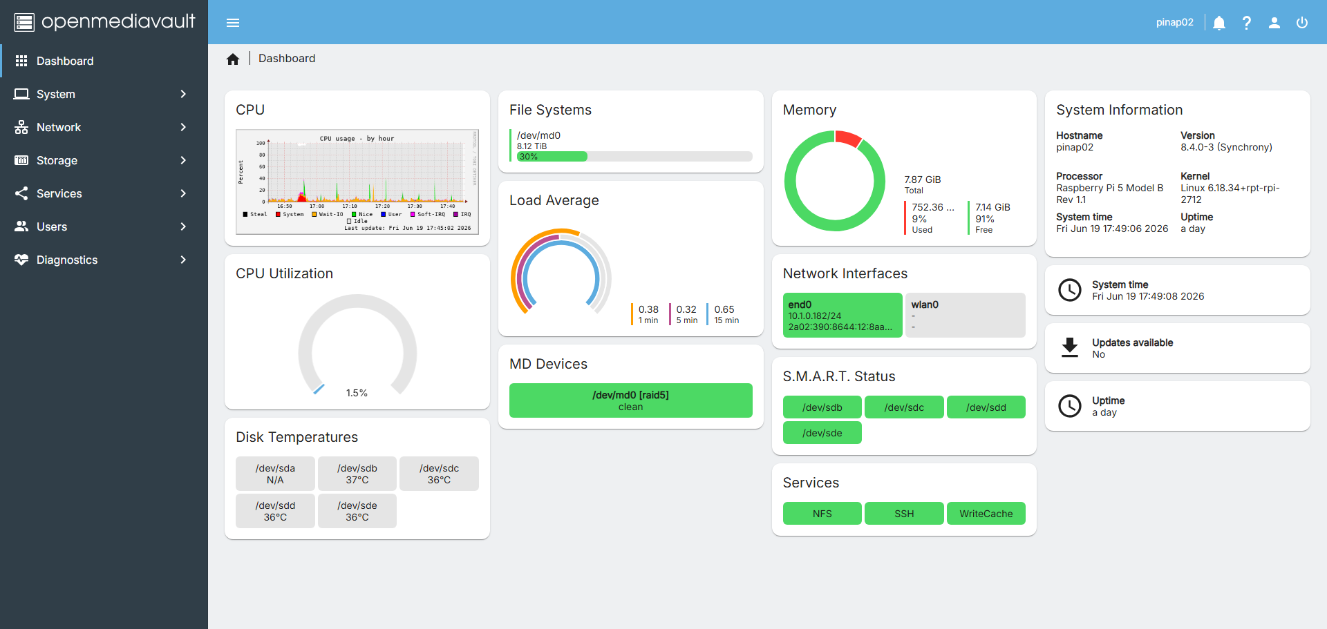
They are fast, quiet and run the latest open source software. This is a great way to squeeze some extra life out of my old QNAPs and provide reliable RAID Storage for years to come.
If there is demand for the conversion kits on Tindie, and I sell more than 20 or 30, it might motivate me to design and build a customer PCB that fits in the exact space the old QNAP motherboard did, removing the need for any major alterations, soldering, or dremelling of the QNAP.

Message me if you would buy a drop in conversation PCB for your QNAP, running a Raspberry Pi 5 compute module. If there is enough demand, maybe I’ll run a Kick Starter.

