I found this online. A robot developed at ETH Zurich. It is brilliant and beautiful. I had to share …

I found this online. A robot developed at ETH Zurich. It is brilliant and beautiful. I had to share …
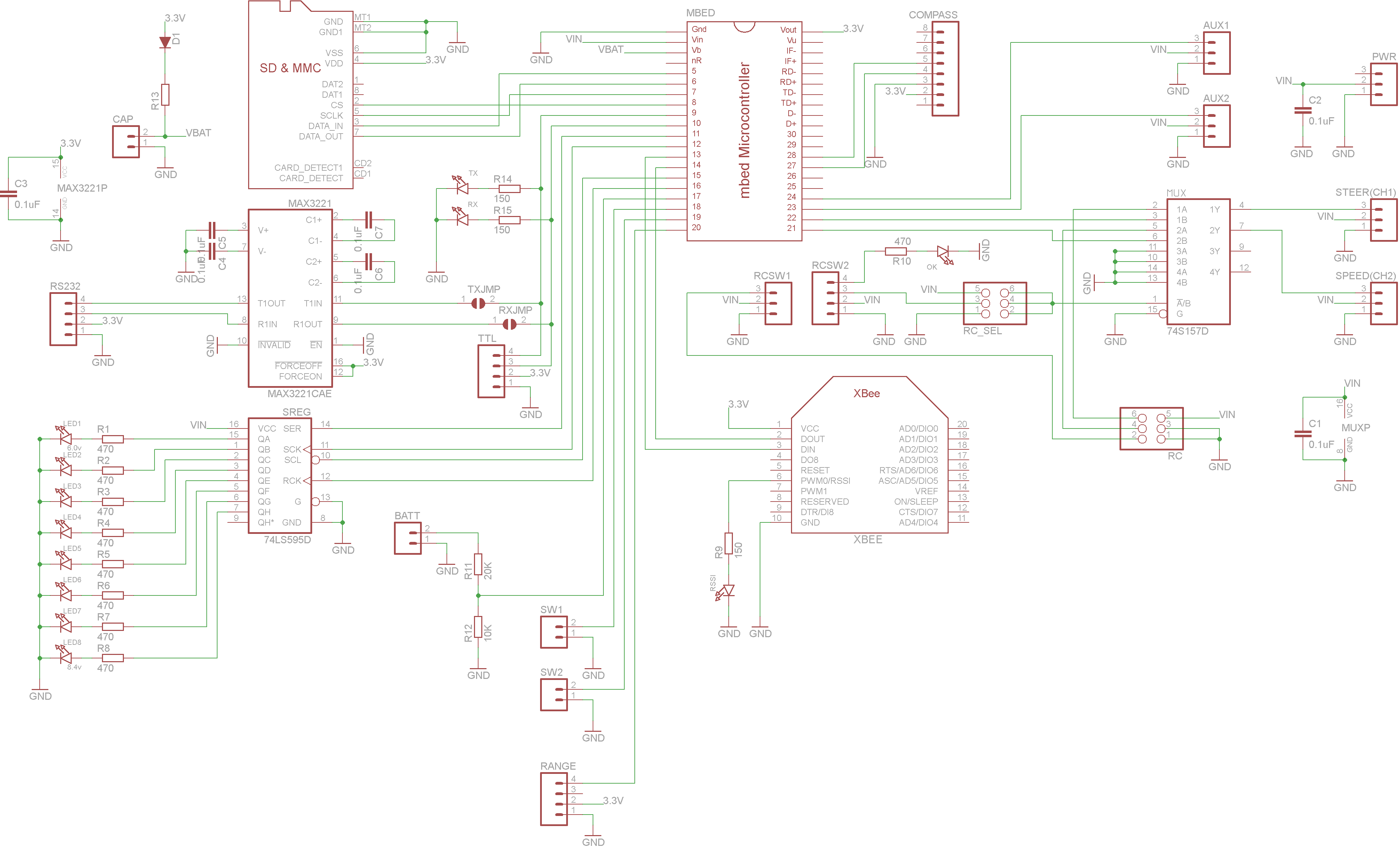
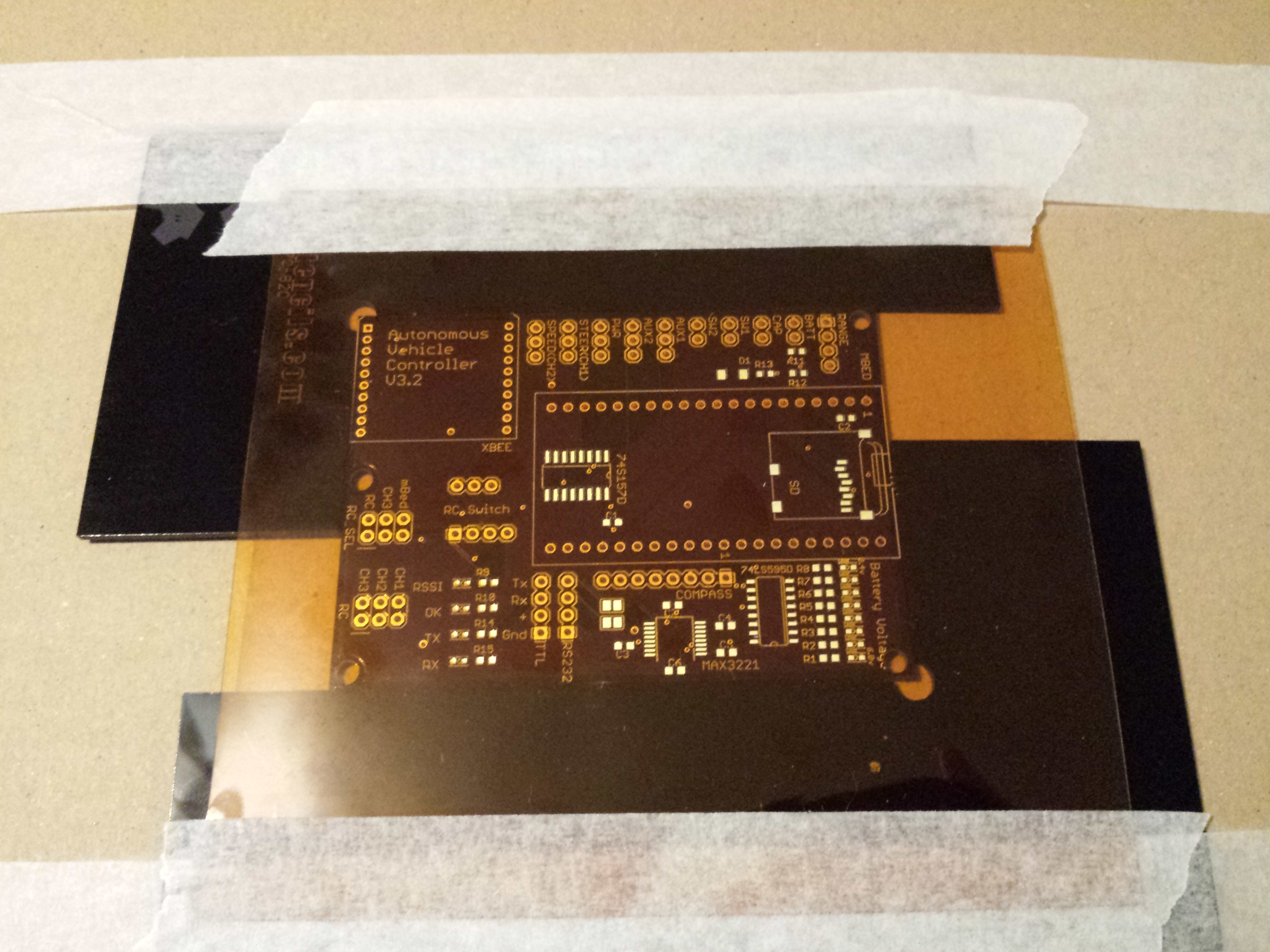
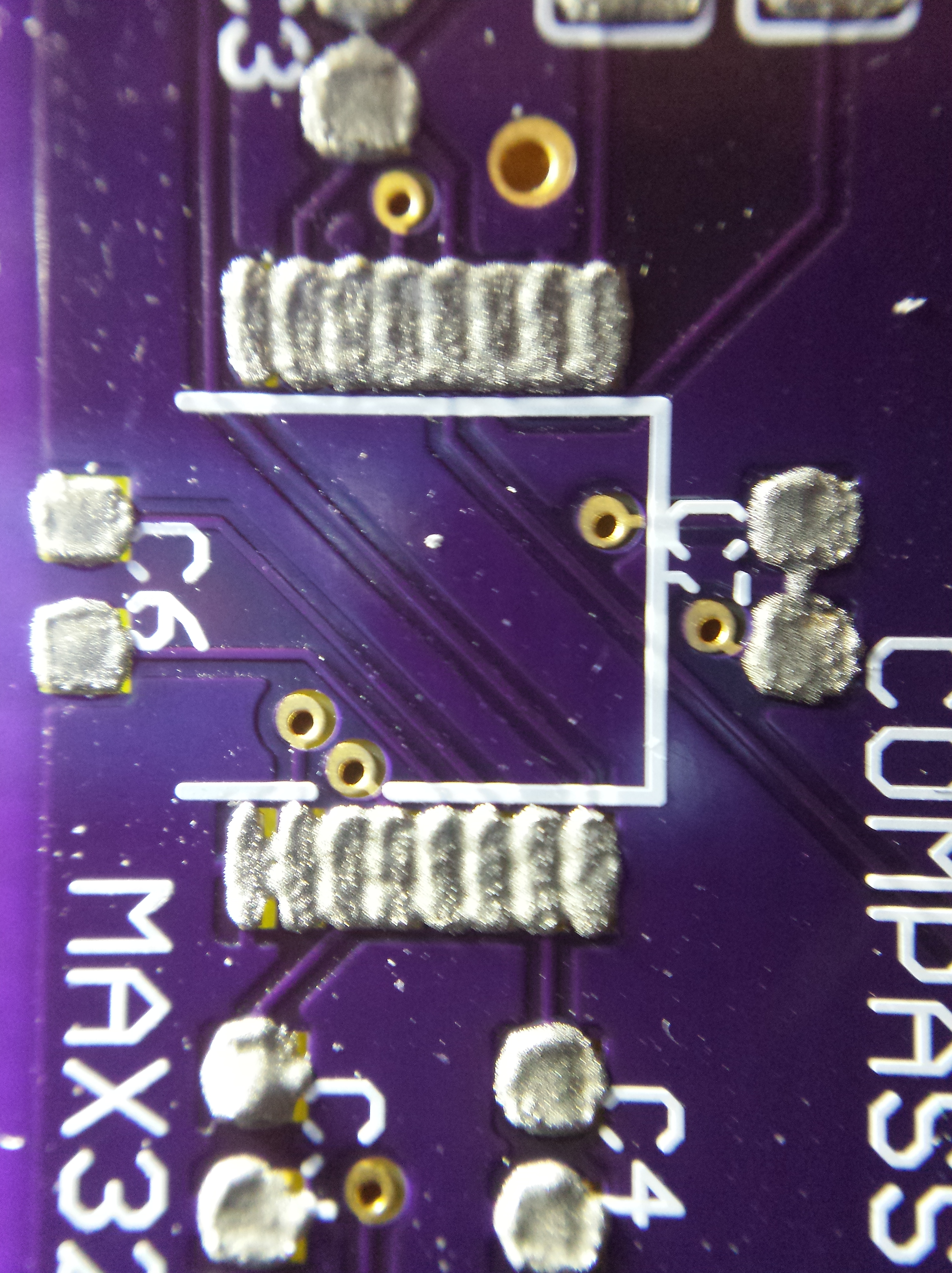
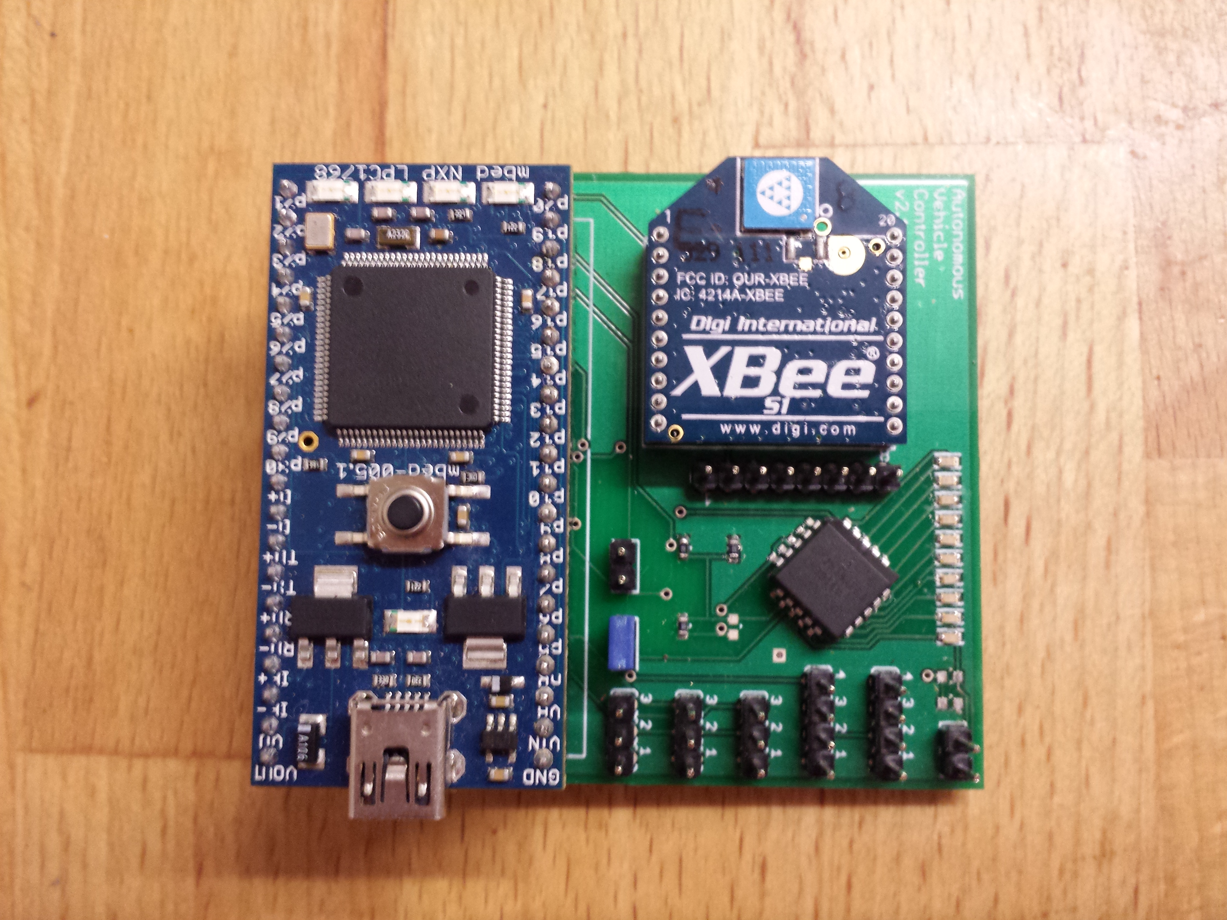
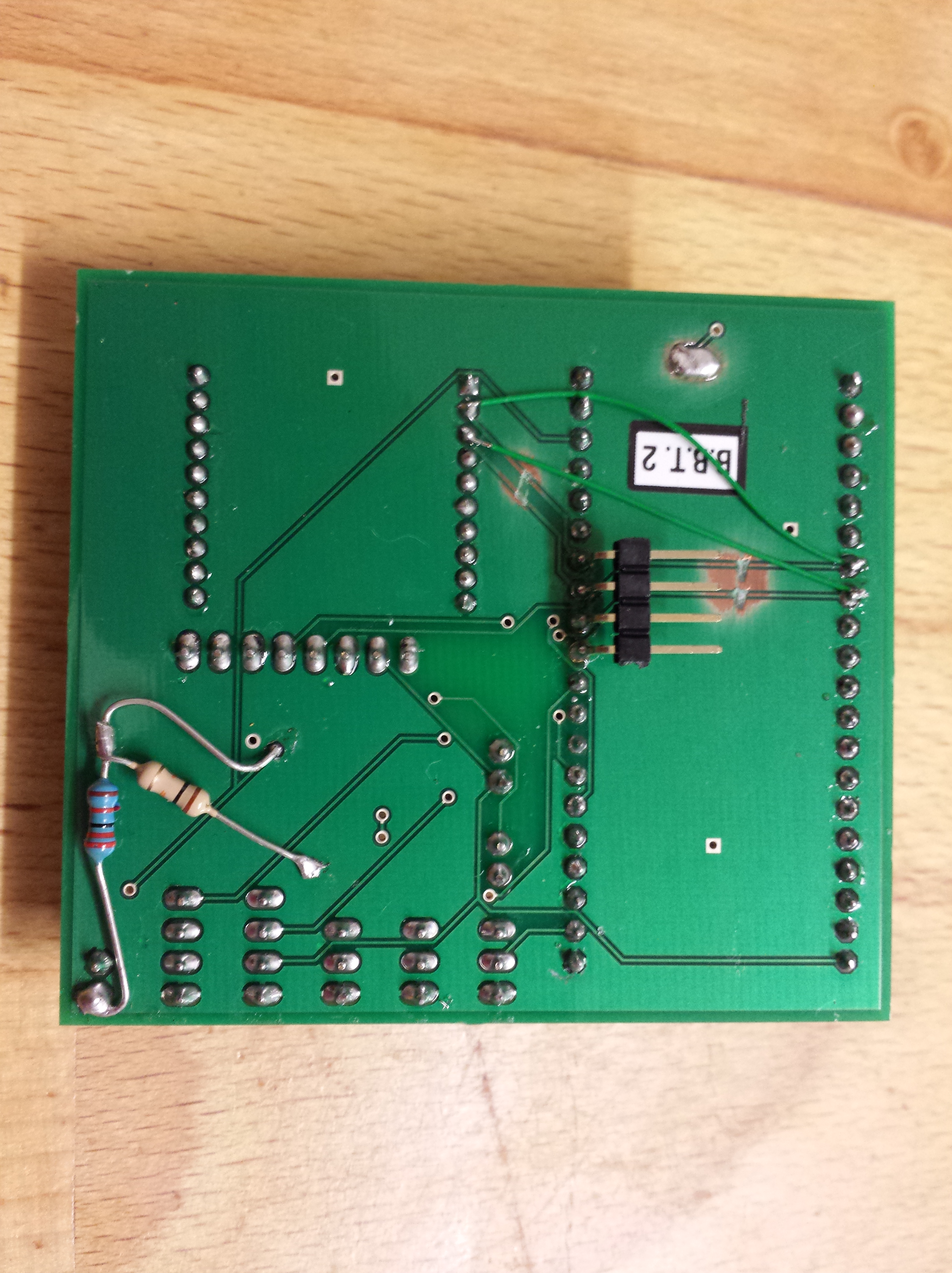
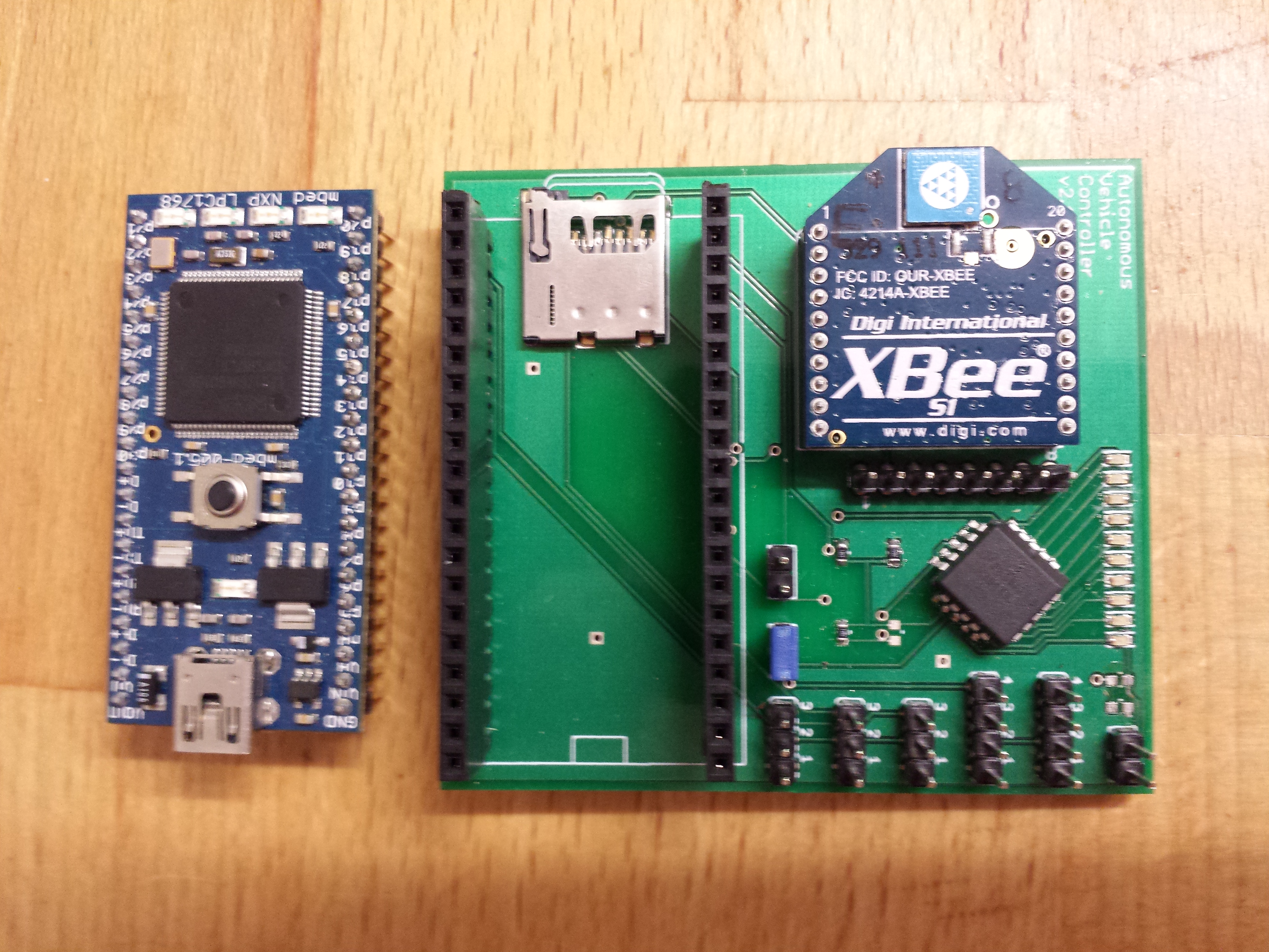
The Sparkfun Autonomous Vehicle Competition this year was lots of fun, as usual. I ran a similar setup to last year, with the same chassis, mBed microcontroller, Magnetometer & GPS. The only difference was a new controller PCB with some extra features, and some changes in the code. The new control board has some incremental improvements from last year, with on-board battery monitor, better layout, built in Mux to multiplex RC and Autonomous control, and an on-board RS232-TLL converter (MAX3221).
AVC 2014 controller PCB v3.2
AVC 2014 controller board v3.2
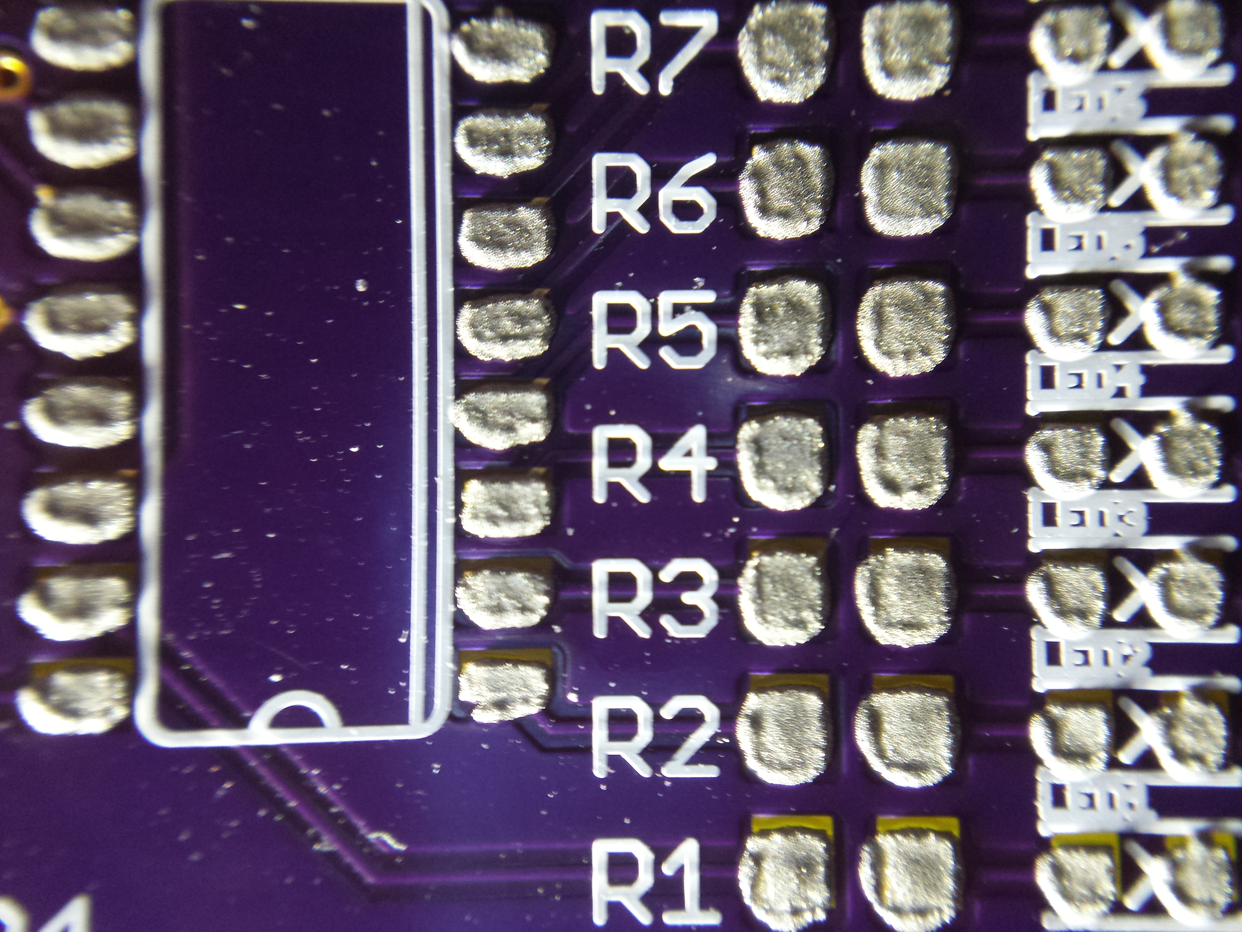
The battery monitor uses a shift register to control the 8 LEDs, so I only need 4 IO lines to control 8 LEDs. The mux uses a 74S157D to multiplex the PWM lines from the RC receiver and mBed out to the RC car steering servo and speed controller. By changing the mux select line, I can control the RC car from the RC controller or the mBed, either forced with a jumper (RC_SEL) or by using channel 3 on my RC transmitter. To decode the channel 3 signal and give me a digital output I use a Pololu RC Switch with Digital Output.
The other useful addition was a 1F super capacitor, attached to the vBAT pin on the mBed. One problem from last year was that all my log files were dated “1/1/1970” as when the mBed boots the clock isn’t set, and I create the log file on boot. I set the clock once I have a GPS lock, with the time from the GPS, but until I have GPS lock, I don’t know what the time is. The mBed has a real time clock, I just need to keep it powered between power downs.
Supplying 3.3v to vBAT keeps the RTC running, even when the main power is off. Usually, you would use a small lithium coil cell, but I had just bought some super caps to play with and they seemed perfect. I used a diode and resistor from the 3.3v power rail to charge the super cap while the power is on and limit the charge current. It works perfectly and kept the clock running for days while the main power was discounted. Now, all my log files have the correct date and time, and once I get a good GPS lock, I reset the RTC, just in case it has drifted.
The bot was ready a couple of weeks before the competition, but as usual, I didn’t have time to do much testing, and my flight only got in to Boulder the night before the competition, so I couldn’t spend the day before at the course. The day of the competition arrived and I got there early to setup and do some last minute testing.
I was in group 7 of the Peloton class. Team : “Mostly Robots”. Robot : “Eleanor”.
There are 3 heats (3 attempts at the course). The are timed, with bonus points for navigating obstacles.

AVC Ground Course ((c) Sparkfun)
Heat 1 got off to a good start. I’m always apprehensive as the bot approaches the first corner. Anyone can build a bot that just drives in a straight line and crashes in to the fence. Turning at the first corner autonomously is a good feeling ! 🙂 The bot was swerving badly on the straight, more than last year. Same old magnetometer issues from last year, but it turned perfectly on the 1st corner. Its programmed to avoid the barrels and zig-zag through them, which it did, and made the 2nd corner. However on the 3rd straight it started to wobble more and zig-zag quite badly instead of driving in a straight line. It made the 3rd corner, but then started to get a bit confused. It spun round in circles a couple of times, then crashed in to a bollard. Disappointing, but not bad for a first run.
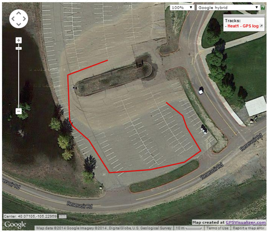
AVC 2014 – Heat 1 GPS log
The less said about heat 2 the better :-). It all went wrong, and straight off the start line the bot crashed in the kerb.
Heat 3 started well, the bot made the 1st corner, avoided the barrels and made the 2nd corner. But on the back straight got confused again and crashed in to the kerb.

AVC 2014 – Heat 3 GPS log
In the end, a fun but disappointing day, as I know the bot can navigate autonomously, as it makes it round three quarters of the course, but the gremlins stopped me from completing all of the three heats.
I came 14th overall out of 25 in my class. Respectable, but I could have done better.
The problem is always the magnetometer. I need to find some time before the next event to work on fine tuning it and experimenting with some different positions to stop interference from the car’s motor and servos.
Roll on next year ! 🙂
This blog is mostly about robots, but not exclusively. 🙂
I needed an NTP server at home, as my security cameras were drifting out of sync. So, I thought I’d create a Stratum 1 NTP Server, with a Raspberry Pi and a GPS receiver.
There are lots of guides on the web, so I just followed the instructions, but it was very easy, once you understand the basics. There are two ways to synchronise the time on the Raspberry Pi to a GPS receiver. The first is just to use the GPS NMEA data to get the time. With a 1 Hz update, you have be accurate to about a second. However, some GPS receivers provide a pulse-per-second output, that provides a digital signal every second that can be attached to a hardware interrupt and this can be accurate to a microsecond.
Nearly all the instructions I used came from here :
I did a couple of other things too, as I had trouble keeping my Raspberry Pi’s running for longer than 3 months on an SD card. After 3 months of being continuously on, I usually got SD card corruption and the server died. I decided to switch this Raspberry Pi to use a USB flash drive to the filing system, and the SD card, just to boot.
The instructions for using a USB flash filing system are here :
I did this first, then configured the GPS / NTP. For this post, I’ll ignore the USB configuration, and it’s not relevant to the GPS / NTP install. It’s up to you if you need it. I’ve heard of lots of people that have run a Raspberry Pi for over a year on an SD card without any issues, and others who have had the same issues as me, with no more than a few months without file system corruption.
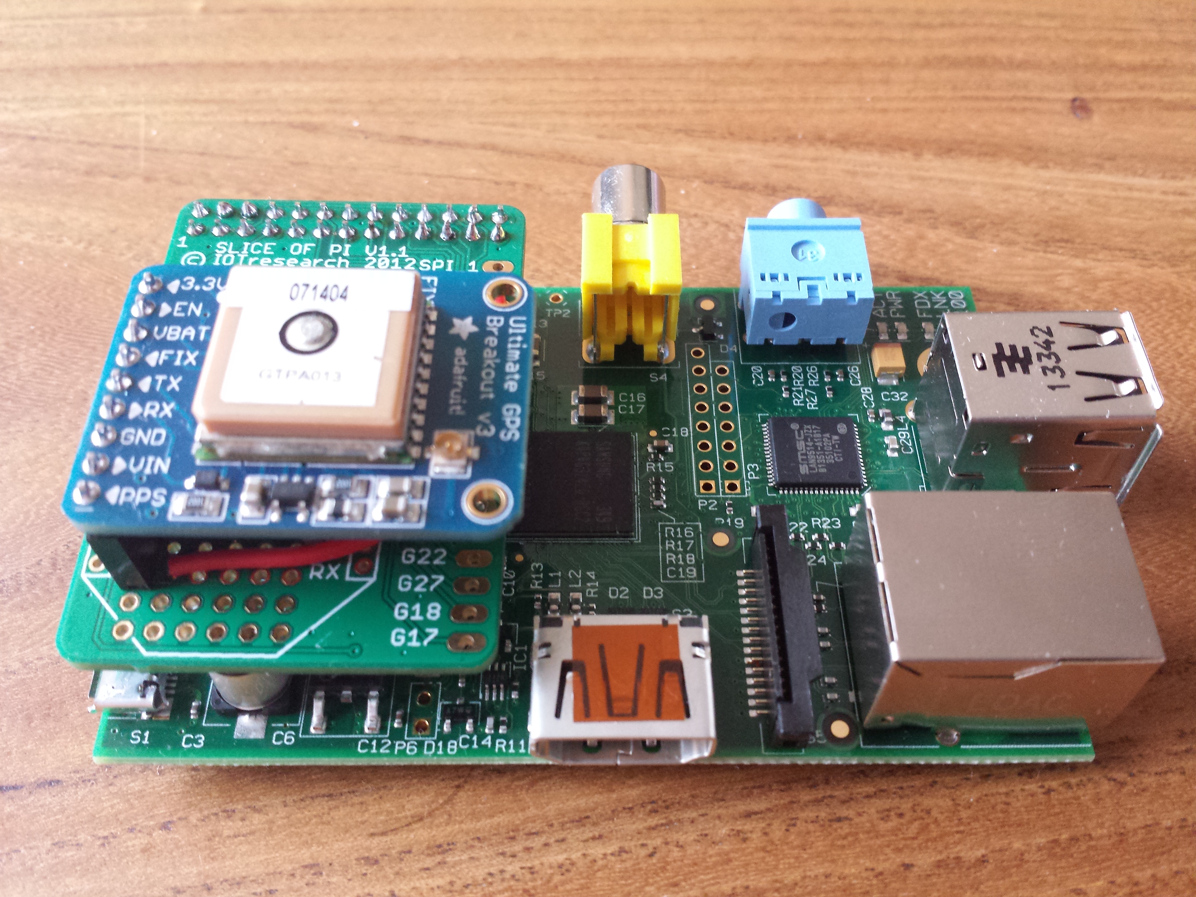
The first thing to do is connect the GPS receiver to the RPi. I used an Adafriut Ultimate GPS breakout board. It has lots of useful features; it’s cheap, it’s easy to connect as it has 0.1” headers, it has a PPS output, it’s 3.3v and it has an external aerial mount.

Adafruit Ultimate GPS Breakout Board
The only problem I found with these GPS units is I couldn’t find a way to permanently change the baud rate. If you set the baud rate on the GPS receiver, the setting doesn’t survive a power cycle. If anyone knows how to do this, let me know. Even in production I am running the GPS at 9600 baud. I would have preferred to run it at a faster rate, which would give better accuracy as the NMEA data can be processed faster. But seeing as the clock is set using the PPS, its not a major issue.
I used a Slice of Pi prototype board to make it easy to connect the GPS to the Raspberry Pi. The wiring is straight forward, 3.3v and Gnd, Tx & Rx, and the PPS connected to GPIO pin 8.

Slice of Pi prototype board
I also have a Power Over Ethernet switch, so I added a PoE power adapter, so the Raspberry Pi would have minimal wiring. I bought a plastic box from Maplins and mounted the PoE adapter, RPi, GPS and external GPS connector all in the box. The box had a clear plastic lid, which also means you can see the RPi in action.

Power Over Ethernet adapter
Assembled Raspberry Pi NTP Server

Assembled Raspberry Pi NTP Server in case with PoE
Once the hardware was attached, the software configuration follows the instruction linked above.
Disable console output to serial
sudo vi /boot/cmdline.txt
find this :
dwc_otg.lpm_enable=0 console=ttyAMA0,115200 kgdboc=ttyAMA0,115200 console=tty1 root=/dev/mmcblk0p2 rootfstype=ext4 elevator=deadline rootwait
and edit it to this :
dwc_otg.lpm_enable=0 console=tty1 root=/dev/mmcblk0p2 rootfstype=ext4 elevator=deadline rootwait
Disable the login prompt
sudo vi /etc/inittab
find the line near the end
T0:23:respawn:/sbin/getty -L ttyAMA0 115200 vt100
add # to comment it out.
#T0:23:respawn:/sbin/getty -L ttyAMA0 115200 vt100
I need my NTP server to have a static IP
If you use DHCP, remove “ntp-servers” from the “request” line in /etc/dhcp/dhclient.conf
Remove /var/lib/ntp/ntp.conf.dhcp if present
sudo vi /etc/network/interfaces
Edit the following entry:
iface eth0 inet dhcp
Change it to (using your local network settings):
iface eth0 inet static
address 10.1.0.128
netmask 255.255.255.0
gateway 10.1.0.1
network 10.1.0.0
broadcast 10.1.0.255
reboot…
At this point you should see the GPS NMEA data coming from the serial port. Test it like this :
sudo cat /dev/ttyAMA0
If you dont see NMEA data, go back and check your wiring and baud settings.
sudo apt-get install gpsd gpsd-clients python-gps
sudo gpsd /dev/ttyAMA0 -F /var/run/gpsd.sock
test it recieves GPS data :
sudo cgps –s

+-------------------------------------------++---------------------------------+
|    Time:       2014-07-07T22:34:15.000Z   ||PRN:   Elev:  Azim:  SNR:  Used: |
|    Latitude:    51.501114 N               ||  20    73    246    32      Y   |
|    Longitude:   -0.142448 W               ||   1    72    117    44      Y   |
|    Altitude:   99.8 m                     ||  32    61    068    51      Y   |
|    Speed:      0.0 kph                    ||  11    45    142    38      Y   |
|    Heading:    67.1 deg (true)            ||  17    43    296    21      Y   |
|    Climb:      0.0 m/min                  ||  33    29    199    00      Y   |
|    Status:     3D FIX (10 secs)           ||  23    28    180    00      Y   |
|    Longitude Err:   +/- 4 m               ||   4    20    294    28      Y   |
|    Latitude Err:    +/- 3 m               ||  31    12    085    42      N   |
|    Altitude Err:    +/- 9 m               ||  14    11    035    17      N   |
|    Course Err:      n/a                   ||  28    08    250    00      N   |
|    Speed Err:       +/- 31 kph            ||  13    02    191    00      N   |
|    Time offset:     0.662                 ||  19    01    161    00      N   |
+-------------------------------------------++---------------------------------+
sudo dpkg-reconfigure gpsd
The configuration program will ask you a series of questions :
Start gpsd automatically? Yes
Should gpsd handle attached USB GPS receivers automatically? No
Device the GPS receiver is attached to: /dev/ttyAMA0
Options to gpsd: -n
gpsd control socket path: /var/run/gpsd.sock
reboot…
sudo cgps –s
You should get the same output as before. This shows everything is starting up correctly on boot.
Make a backup of the ntp.conf file. Edit the conf file.
sudo cp /etc/ntp.conf /etc/ntp.old.conf
sudo vi /etc/ntp.conf
Remove the IP access restrictions
Comment out :
restrict -4 default kod notrap nomodify nopeer noquery

#restrict -4 default kod notrap nomodify nopeer noquery
Configure NTP to use the UK NTP pool servers.
I’m in the UK. If you’re not, pick the most local pool to you.
Replace:
server 0.debian.pool.ntp.org iburst
server 1.debian.pool.ntp.org iburst
server 2.debian.pool.ntp.org iburst
server 3.debian.pool.ntp.org iburst
With:
pool uk.pool.ntp.org iburst
Add the local NTP server from your ISP.
server ntp.eclipse.co.uk iburst
Restart NTP and check its working.
sudo /etc/init.d/ntp restart
sudo ntpq -p -n

     remote           refid      st t when poll reach   delay   offset  jitter
==============================================================================
*213.249.130.101 10.100.94.8      2 u    3   64  377  120.208   37.434  53.254
+87.124.126.49   195.66.241.3     2 u   10   64  377   32.008   -8.111  99.007
 82.219.4.30     .INIT.          16 u    - 1024    0    0.000    0.000   0.000
 217.10.144.130  .INIT.          16 u    - 1024    0    0.000    0.000   0.000
-151.230.30.222  103.7.151.4      2 u   25   64  377   47.016    0.743  98.865
Basic NTP is now working, but without GPS. Even without GPS, its still accurate to about 37ms.
Edit ntp.conf
sudo vi /etc/ntp.conf
add :
# Server from shared memory provided by gpsd
server 127.127.28.0 minpoll 4 maxpoll 4
fudge  127.127.28.0 time1 0.000 refid GPS
Restart NTP and check its working.
sudo /etc/init.d/ntp restart
sudo ntpq -p -n

     remote           refid      st t when poll reach   delay   offset  jitter
==============================================================================
*127.127.28.0    .GPS.            0 l    7   16  377    0.000   -353.23 15.024
-213.249.130.101 10.100.94.8      2 u   62   64  377   52.603   -3.554  77.753
-87.124.126.49   195.66.241.3     2 u    6   64  377   42.207   -5.468  78.352
 82.219.4.30     .INIT.          16 u    - 1024    0    0.000    0.000   0.000
 217.10.144.130  .INIT.          16 u    - 1024    0    0.000    0.000   0.000
+151.230.30.222  103.7.151.4      2 u   16   64  377   47.016    0.743  58.425
Adjust the time1 fudge offset to compensate for drift. The GPS NMEA input is taking about 350ms to process.
fudge 127.127.28.0 time1 0.350 refid GPS
Restart NTP and check again. The GPS inout should be more accurate. (now only 11ms out)
     remote           refid      st t when poll reach   delay   offset  jitter
==============================================================================
*127.127.28.0    .GPS.            0 l    3   16  377    0.000   11.721  38.208
+213.249.130.101 10.100.94.8      2 u   33   64  377   72.434    1.227  98.033
-87.124.126.49   195.66.241.3     2 u   48   64  377   50.215   -0.824  76.877
 82.219.4.30     .INIT.          16 u    - 1024    0    0.000    0.000   0.000
 217.10.144.130  .INIT.          16 u    - 1024    0    0.000    0.000   0.000
-151.230.30.222  103.7.151.4      2 u   56   64  377   48.522    0.481  50.334
For more details see : http://vanheusden.com/time/rpi_gpio_ntp/
sudo wget http://vanheusden.com/time/rpi_gpio_ntp/rpi_gpio_ntp-1.3.tgz
sudo tar -zxvf rpi_gpio_ntp-1.3.tgz
sudo cat rpi_gpio_ntp-1.3/readme.txt
Read the instructions. You must build and install the program:
sudo cd rpi_gpio_ntp-1.3
sudo make install
You probably want to let rpi_gpio_ntp start at boot.
To do so, edit /etc/rc.local
sudo vi /etc/rc.local
and add the following line (BEFORE the “exit 0” statement and AFTER the “#!/bin/sh” line):
/usr/local/bin/rpi_gpio_ntp -N 1 -g 8
This assumes that the PPS signal of the GPS is connected to GPIO pin 8 which is physical pin 24.
reboot…
Edit ntp.conf
sudo vi /etc/ntp.conf
add :
# Server from PPS module
server 127.127.28.1 minpoll 4 maxpoll 4 prefer
fudge  127.127.28.1 refid PPS
Restart NTP and check its working.
sudo /etc/init.d/ntp restart
sudo ntpq -p -n

     remote           refid      st t when poll reach   delay   offset  jitter
==============================================================================
+127.127.28.0    .GPS.            0 l   15   16  377    0.000   65.031  38.403
*127.127.28.1    .PPS.            0 l   14   16  377    0.000    0.001   0.006
x213.249.130.101 10.100.94.8      2 u   12   64  377   79.034   16.835  82.844
+87.124.126.49   195.66.241.3     2 u   26   64  377   28.945    1.316  42.948
 82.219.4.30     .INIT.          16 u    - 1024    0    0.000    0.000   0.000
 217.10.144.130  .INIT.          16 u    - 1024    0    0.000    0.000   0.000
-151.230.30.222  103.7.151.4      2 u   39   64  377   36.126    2.120  57.079
This shows the Raspberry Pi system clock is accurate to 1us !!
My final ntp.conf file :
driftfile /var/lib/ntp/ntp.drift

statistics loopstats peerstats clockstats
filegen loopstats file loopstats type day enable
filegen peerstats file peerstats type day enable
filegen clockstats file clockstats type day enable

# Server from shared memory provided by gpsd
server 127.127.28.0 minpoll 4 maxpoll 4
fudge  127.127.28.0 time1 0.550 refid GPS

# Server from PPS module
server 127.127.28.1 minpoll 4 maxpoll 4 prefer
fudge  127.127.28.1 refid PPS

# You do need to talk to an NTP server or two (or three).
server ntp.eclipse.co.uk iburst

# pool.ntp.org maps to about 1000 low-stratum NTP servers.  Your server will
# pick a different set every time it starts up.  Please consider joining the
# pool:
pool uk.pool.ntp.org iburst

# By default, exchange time with everybody, but don't allow configuration.
#restrict -4 default kod notrap nomodify nopeer noquery
#restrict -6 default kod notrap nomodify nopeer noquery

# Local users may interrogate the ntp server more closely.
restrict 127.0.0.1
restrict ::1
The final NTP Server installed in my garage, with an external GPS aerial on the roof.

Assembled Raspberry Pi NTP Server in case with PoE
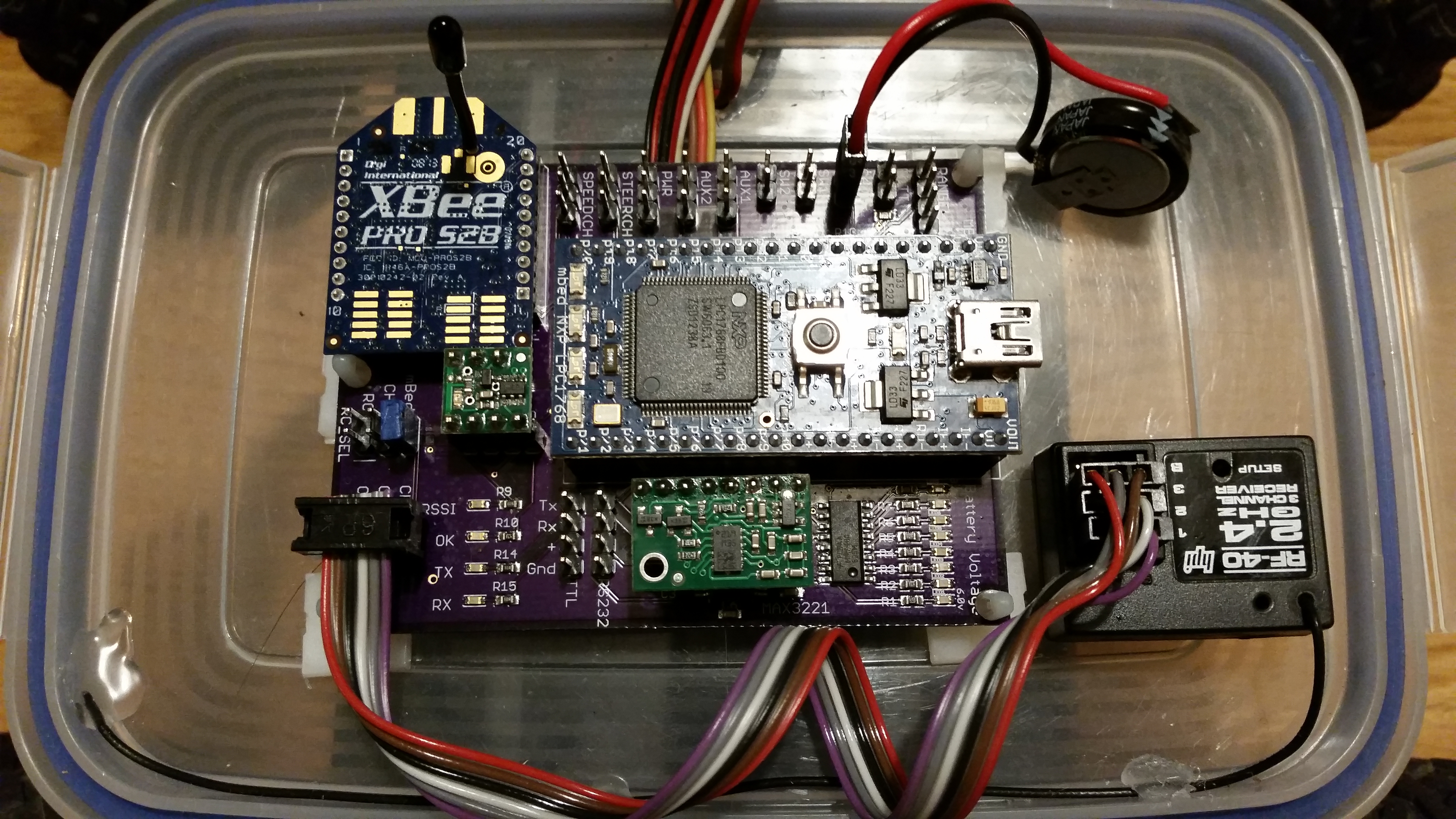
So, my bot is ready (ish) for this weekend. I have the new controller board installed. Only found 3 mistakes (and isolated ground, the wrong supply voltage on the RS232 header, and the SD card holder hasn’t soldered correctly.) everything else worked. I have fixed the first two, but I cant reflow the board again to fix the SD card holder, as I’ve already soldered all the plastic headers on. I can live without the SD card, I will use the internal flash disk on the mBed. It has a few restrictions, but I only store a waypoint file and a config file on it.
AVC 2014 Robot
I’m running an updated version of last years code. But seeing as it worked last year, I’l stick with it and improve it slightly. Now I have a reliable xBee connection, the compass calibration process is much easier. No more cables. I will try this year to calibrate the compass, with the main motor running (albeit slowly) to ensure any interference from the motor is present in the calibration settings.
However, I’ve been so busy recently, that again I have not manage to complete a full outside test of the bot before getting on a plane for Boulder ! 😦 the first full test will be in the car park in the hotel the night before.
Not to self – find more time to tinker next year before the competition !
Wish me luck …
Usually I build my printed circuit boards by hand. Once the boards are fabricated, I apply solder paste using the patented “Jon Toothpick Method”, then place the components by hand using tweezers. This works fine, as I usually only build 1 or 2 boards. But recently some of the projects I’ve been building have either lots of SMD devices (a recent board had 30+ 0603 resistors), or the devices I’m using are tin, with very small pitch legs (I use SSOP & TSSOP packages, which are very small).
So, I decided to try getting a solder stencil made to use during my next build. I use OSH Park for my PCBs and they recommended OSH Stencils. The stencils were very affordable. They cost about $10 each, and they are about 6.5 sq in. I think they are laser cut Kapton film which according to online review, is pretty durable.
The process of applying solder paste using a solder stencil is pretty simple:
Here are some pictures of the process.

New PCB

PCB Stencil

Align stencil with PCB
Tape stencil in to position

Wipe solder paste across board
Solder paste applied on the pads
Solder paste applied on the pads

After components and soldering

After components and soldering
I’m very pleased with the results. There is almost no solder spilled on the PCB to clean off, you get consistently the right amount of solder paste on each pad and the result looks very professional and neat.
The process was easy and quick. I think I’ll be using stencils with all my future PCB builds. I just need a pick and place robot now … 🙂
This is a video of my first fully autonomous round 1 attempt. I made the first corner and avoided two barrels, but then ran in to the inside fence. I don’t have any footage from the other rounds as my camera gave up shortly afterwards.
This is a video of the first few outdoor test runs of my AVC robot. As you can see, I had a lot of magnetometer issues, but eventually, the last run does make it to the waypoint, albeit a rather scenic route. 🙂
The morning of the competition arrived. After getting up early so I could be at the course as it opened to spend the final hour tuning my way points, I released when I arrived at the venue, I’d left my wallet in the hotel, and had to drive back to the hotel and get it, taking all the time I would have had to practice, driving up and down the motorway in Boulder. 😦
AVC 2013 Ground Course ((c) Sparkfun)

AVC 2013 Waypoints v1
The competition began. I was in heat 8, so I had a good 45 minutes to tinker before my first run. I mounted a GoPro and double checked my way pints on Google Maps. I was kind of pleased to see that almost no one in the first few heats made it past the first corner. In fact by heat 8, I think only 2 robots had made it round the course, out of about 30.
It was time for my first run. I was actually nervous !? Even thought I knew I wouldn’t win, I wanted to make it round the course, and not look like an idiot. Also I was the only Brit in a sea of Yanks … I need to represent my country ! 🙂
The countdown began, then Go! I pressed the big red button and my bot shot off ! To my surprise and great relief in the right direction !!! and to my amazement, it made the first corner and turned 90 degrees at exactly the right waypoint, on to the second straight. My heart was pounding as my bot swerved to the 2nd way point. I had 3 waypoints on the second straight to avoid the barrels. It swerved and missed the first barrel, I was actually amazed it was working !
I turned again and aimed to miss the second barrel … but then it didn’t straighten up and started to veer in to the centre of the course … within a few seconds it had hit the boundary fencing, and toppled over. Disaster! I was out in the first round mid-way up the second straight.
Not bad all things considered. Seeing as it was the first time all that code had run at the same time, completely autonomously. Although I was disappointed, I was actually quite chuffed it had made the first corner and hit the first three waypoints. My code was working !
During the beak between rounds I debugged the code and analysed the log from the first run. The bot was working, but was veering to the left, so I adjusted the 3rd waypoint to pull the bot further in to the centre of the course.
The second round. Go! I hit the button and my bot shoots off in the right direction again, but where it had neatly turned 90 degree at the first way point on the first round, this time, it span in circles at the first way point, driving in endless circles until it hit a hay bail.
In theory that shouldn’t be possible. The code should have dropped out of the loop when the waypoint was close, plus the circle was also tight, i.e. full lock. There must be something else wrong.
I spent lunch time debugging the logs and analysing the data. To my horror, the magnetometer was completely out of whack. It would reading north to be 90 degree from where it should be. And in various walking tests didn’t even change readings as I rotated the bot. My magnetometer reading were the plague of this project.
I decided to run another calibration over lunch, it takes a while, as I have to change some connections as I can’t do it reliably over xBee, so I run the calibration over a direct serial connection.
It took about 30 mins to complete the calibration and the bot was reading north again. I had about 20 minutes left of lunch to test on the course before the final heat. I pressed the button for a final practice and the bot shot off in the right direction, first waypoint hit, second way point hit, barrel avoided. Third way point hit, this was the furthest I’d ever got on the course. The back straight was perfect. I purposely avoided the hoop, I wanted to get round, and wasn’t so bothered about points. On the third straight, it actually hit the ramp and completed a jump, without toppling. It hit the final corner turned perfectly and flew over the finish line ! I had completed the course perfectly ! Shame it was over lunch in a practice session and no one saw ! 😦 I do have some video from the GoPro to prove it through !
I decide not to touch ANYTHING and wait for the final round. More and more bots were completing the course. Each run they were getting better. It was now or never.
Finally the third round was here. Nate (The Owner of SparkFun!) was my referee for the final round. No pressure then !?
The referee counted down 5,4,3,2,1 – Go ! I paused slightly to let the faster bots shoot off before me, to try and minimise any potential collisions. Previous rounds had a number of collisions right off the start line, where out of control bots took smaller bots out completely. I saw one completely smashed to pieces. My bot shot off in the right direction … turned perfectly on the first courser … weaved perfectly in through the barrels, detoured slightly wide at the second corner, my heart pounded as it headed for the fence, but with a meter to go, it turned sharply and headed off past the hoop. It started to oscillate on the back straight – shame I never got the PID controller tuned I thought – the bot headed straight for the cameraman on the 3rd corner, again with a meter to spare turned sharply 90 degrees and headed down the final straight … missing the jump (shame. It made it perfectly in the practice, and I could have got some bonus points). The curb of the final corner loomed, the bot shimmied perfectly round it, turn sharply on the final straight and headed for the finish line. I held my breath as the bot bounced over the finish line perfectly, running over the SparkFun GoPro that was balanced on the start/finish line capturing the action … 2 or 3 meters after the finish line it ground to a halt. I was so happy ! I think I actually kissed it (which someone caught on camera) 3 months of late nights and constant problems culminated on a perfect run on the final round. I was elated. I’ll post a video …
What’s next ?
I want to finish the bot off, even though the competition is over. Not only to have something ready if I manage to find a way to enter again next year, but also to understand what’s wrong. I still don’t fully understand why the magnetometer is so shonky. It’s not the device, I’ve tried 3 different devices, and they all do the same strange things.
At the competition, nearly all the other bots has their magnetometer in the car, on the main PCB, not floating on a broom handle above it like mine. I need to understand what my issues are.
I want to finish the PID tuning and increase the speed. The RC chassis is very fast, and I’m running at about 1/10th speed. If I can remove the broom handle, the bot won’t topple over so easily and can turn faster. I also want to include a proportional speed control so the bot accelerates fast if it’s far away and on a straight heading, then brakes to make the turn as it gets close to the waypoint.
I also want to finish the obstacle avoidance, so if I do head for a barrel, I can veer away from it.
All in all and very pleasant way to spend a weekend. I got to talk to lot of interesting people with a similar passion, I got to spend the weekend in 90 degree sunshine and I got to indulge my passion for robotics and spend the weekend geeking out … 🙂
Thanks to everyone at SparkFun for running the event and organising it so well.
Roll on AVC 2014 … 🙂
Other posts in this series :
The mBed versions of the AVC PCBs arrived. I built the first version, with surface mount components in my oven at home. It works first time. It turns out I made one mistake on the PCB, using the wrong ratio SMD resistors with the battery divider in to the mBed, so I had to take them off and modify it with standard through hole resistors, as I couldn’t hand solder the 0602 surface mount resistors. I made the modification for the SPI connection for the IMU, and swapped a couple of sensor to different pins to give me SPI and Serial in the right places.
AVC 2013 mBed Custom PCB
AVC 2013 mBed Custom PCB
AVC 2013 mBed Custom PCB
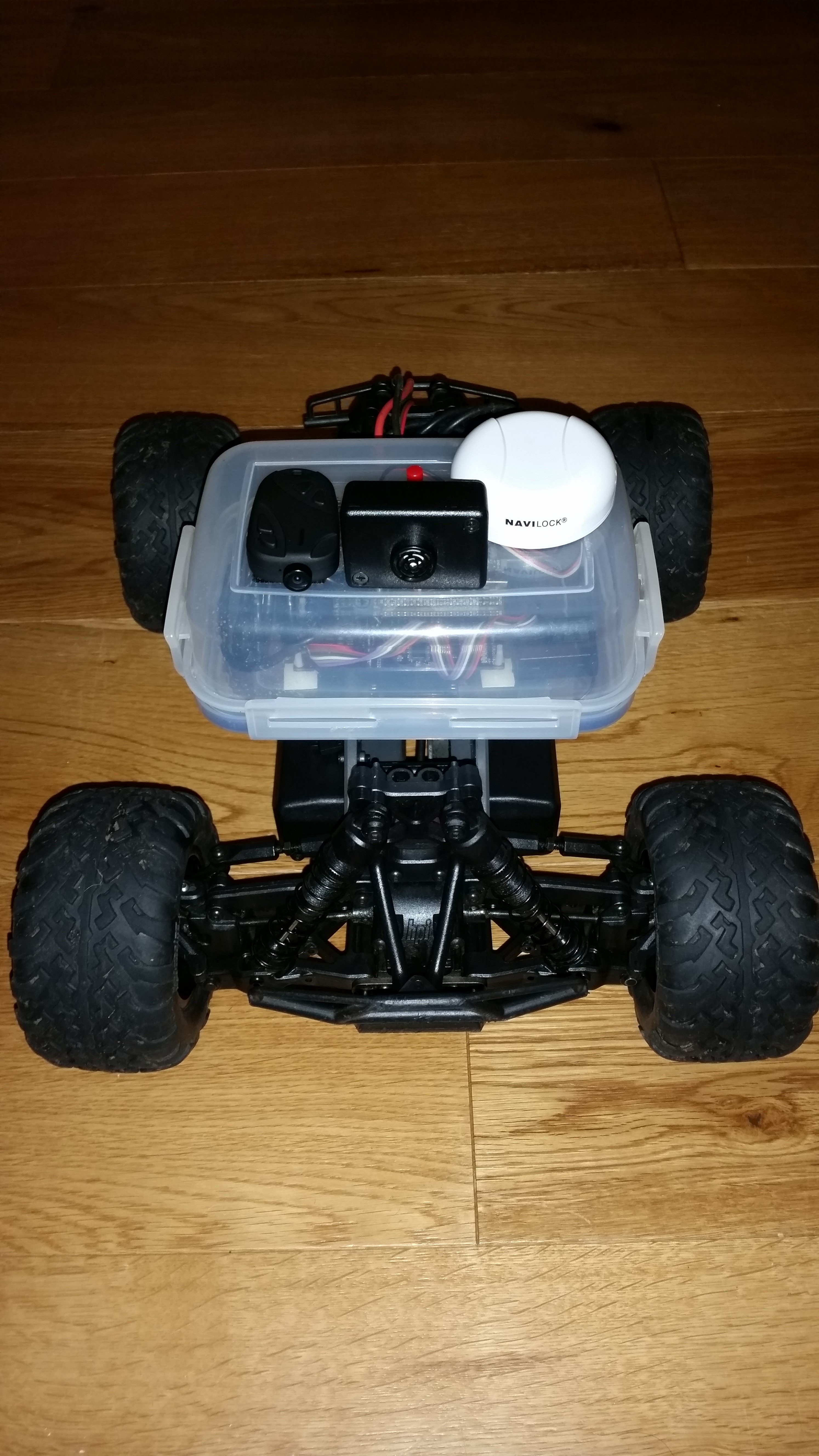
I mounted the circuit in a Tupperware box on the car to keep it water tight.
My first outside test of the complete system was very exciting, but a little disappointing. Not only did I manage to run my wife over with the car, giving her a nasty bruise, but also the car seemed to like to take the scenic route to the way point, rather than a more direct route. All down to magnetometer issues again. I was still getting erroneous and unstable readings. In fact this plagued me from start to finish on this project, and still hasn’t gone away.
The only solution I have found to improving the magnetometer readings is to re-run the magnetometer re-calibration process regularly (before each run). The numbers always come out slightly different?
The first end to end test of the system in my garden was one week before the competition. I still hadn’t written a lot of the other functions in the code. Sections of the code like; how to tell if I had reached a waypoint, loading way points from SD, obstacle avoidance using the sonar, and tuning the PID parameters. I also hadn’t actually mapped my waypoints for the route I was going to take through the course.
The PID tuning would have to wait. I was getting pretty good steering results just with the “P” terms. This would mean I was in danger of oscillations, but that was the least of my worries. I could hardly drive in a straight line at the moment …
I didn’t have time to write any sonar obstacle avoidance code. I had a plan to read the distance data from the sonar and if an object got within 2 metres, add an offset in to the steering calculation to veer slightly left or right to miss the object. However, I hadn’t quite worked out how to tell if I had “passed” it to remove the offset, as I only had a forward facing sonar. The other option was to just stop the bot if an object appeared less than 20cm in front of the bot, stop, turn a few degrees, go forwards, then continue under GPS control… I’ll get round to adding this later …
I arrived in the US for a conference about a week before the competition and spent the evenings in the hotel writing the missing code. I wrote a basic file reader to load way points and basic config data from file, plus as my xBee worked for about 2m at best, I wrote a simple logging function, which meant I had some debug data after each test run to investigate. My waypoint algorithm was relatively simple;

Way Point Diagram
I didn’t have time to write the obstacle avoidance code or tune the PID in time for the competition.
The day before the competition I spent the afternoon at the location planning the course and testing the code. I rewrote my magnetometer code again, this time using my own simple trigonometry rather than the library function. Plus I debugged the “hitting the way point” logic. By sunset, I’d navigated to a series of way points for the first time, but still careering off course occasionally. In addition I suddenly remembered that I hadn’t compensated for magnetic vs. true north, so added some Magnetic deviation code. This link has a great calculator for magnetic variance. It shows that Colorado has a deviation of about 8 degree, which would have been a big issue if I hadn’t remembered to compensate for it.
Other posts in this series :
The basic prototype worked on the bench, but as I built it on to the chassis, it started to have issues. The magnetometer would give very random and unreliable readings. I kind of assumed I’ve get some interference, but this was reading north sometimes 180 degree out. In addition, the reading changed when the motors ran and the servos moved. I assumed I was getting magnetic flux from the motors and servos, and this was interfering with the magnetometer. However, without the motors running, I was also getting bad drift from the magnetometer. For example, I would point the car north, take a magnetometer reading, then rotate the car 360 degrees, the reading wouldn’t give me a 360 change. When I get back to north I would read 280 odd degrees, in addition, if I did the same experiment in different places in the room, or at different times, I got different readings. The magnetometer be useless if I couldn’t reliably know where “north” was.
The xBee also had issues, and seemed to only work up to about 1-2m away … which wasn’t very useful. I only had 1mW series 1 devices, which on the data sheet said they’d get 600m, so I expected a bit better than 2m, but I assume this was also due to interference. This wasn’t a deal breaker, as most of the testing could be done with the car no actually driving. All the debugging was around the steering, so 2m was fine to just not have a cable in the way. But it was frustrating … I had to follow the car around carrying the laptop, instead of just sitting in the garden at a table and taking reading as it drove around.
I stuck with the xBee but I moved the magnetometer away from the main board and chassis, to try and reduce the interference. I assumed the interference was magnetic flux coming from the huge brushless motor and large powerful steering servo in the car. If I mounted the magnetometer away from these, perhaps I’d get a more reliable reading. And so was born “broom-handle-bot”

SparkFun AVC 2013 autonomous robot
While working on the prototype I was also researching better GPS solutions. The basic GPS module I was using only had an accuracy of about 2-5m. This would be tricky to avoid a barrel or hit a jump 1m wide. I had stumbled across SBAS while research GPS issues and this potentially could give me accuracy down to 1-2m. Much better. You can read the wiki page for more details, but effectively (IIUIC) the SBAS system sends a separate signal from a different set of satellites that contains data to improve the accuracy of the main GPS signal. It compensates for atmospheric interface, and other transmission errors. There are different SBAS systems in different parts of the world, WAAS in North America and GLONASS in Europe. I would need a GPS receiver that supported both. Again, with some googling, I found NaviLock and the NL-622MP MD6 GPS Receiver. The data sheet confirmed it supported WAAS and GLONASS, it uses the latest u-Blox chipset, and came in a handy mountable self-contained puck. I ordered one and it arrived. The only downside was the output was RS232 (+/- 15v) not TTL, so I’d need a level shifter board to connect it to the mBed. If I had spent more time looking, they do do a TTL version, which would have been easier …
The very first test of the new GPS puck was transformational. The old GPS wouldn’t get a lock inside my house, which made testing a real pain. I would have to write the code, upload it, then disconnect the system, walk outside in to the garden, test it in the cold, then come back in and debug it, then repeat. This wouldn’t have been so bad, if this was on a Sunday afternoon, but due to my job and family commitments, nearly all my tinkering was done at night, between the hours of 10pm and 2am. It was also the back end of winter, and still snowy some weekend. Testing in the garden at midnight in the snow wasn’t fun.
The new GPS got a lock inside. Plus it got a lock really quickly, within seconds. The old GPS took minutes. It was clear from the first few outside tests that the accuracy was much better and the reading more stable. The GPS used the uBlox 6 chipset, with came with a very detailed and advance desktop config and debug utility.
The basic system was working. However I still had magnetometer issues. The reading would vary wildly if the magnetometer was close to the car. Even if it was some distance way, it wasn’t reliable. It would point north, then I would rotate it 180 and it wouldn’t point S, it would read 160 degrees, then I point it north again and it would read -30. If I rotated it 360 degrees sometimes it didn’t move, sometimes it rotated 250 degrees. I tried lots of different configurations. Even on the bench with no magnets or metal close it wasn’t reliable.
After some extensive Googling, it seemed I need to perform a calibration. This would calibrate out basic interference if the interference was constant, like a steel mounting screw that was always in the same relative position to the sensor. This link explains the process. You take lots of readings from every orientation, imaging mounting the sensor on gimbals and spinning it on all axis, so the tip of the sensor scribes the outline of a sphere. Ideally you want a data cloud of points in all orientations from all three sensors; x, y & z.
Once you have the data set you need to do three things;
Imagine a point cloud that is slightly oval shaped. The normalisation process shifts and scales the cloud so it’s a perfect circle, orgined around zero.These scaling and offset numbers are then used to scale the raw reading to give better accuracy.

Compass Calibration – Before

Compass Calibration – After
This worked to an extent, and the magnetometer was noticeably more accurate and stable, but I still had problems. So I thought I’d tried a different approach. I had an IMU sensor from a previous project. This sensor has 9 DoF (gyro, accelerometer & magnetometer) plus a CPU and contains a kalman filter to process the data. It will give Euler angles, and all I was after was “yaw” – Phi. The issue was the device was not I2C, but serial or SPI. The serial interface had complex packet structure and I didn’t have time to write and debug a parser, so I opted for SPI. I modified the code to read SPI and got a basic Phi reading from the device.
This was more accurate. But it now had a different problem. The issue with yaw calculating with a 9 DoF board, is the yaw cannot use the accelerometer data, as it rotates around the accelerometer axis so it never changes. It can only merge the magnetometer and gyro data. And this is susceptible to gyro drift. This manifested itself in the yaw reading slowing rotating even when the unit was stationary. There was a function in the devices to zero the gyros when the unit was at a known stationary position, but after time the drift returned. That clearly wasn’t going to work.
The final option was to try the same basic magnetometer code, but with these IMU magnetometer readings. You can read all the raw gyro, accelerometer, magnetometer readings, plus the processed (filtered) version, plus the Euler angles from the device.
It turned out the process (filtered) raw magnetometer readings were pretty stable. So I had my final solution. However … about a week before the competition!
Other posts in this series :
