AVC – Problems

The basic prototype worked on the bench, but as I built it on to the chassis, it started to have issues. The magnetometer would give very random and unreliable readings. I kind of assumed I’ve get some interference, but this was reading north sometimes 180 degree out. In addition, the reading changed when the motors ran and the servos moved. I assumed I was getting magnetic flux from the motors and servos, and this was interfering with the magnetometer. However, without the motors running, I was also getting bad drift from the magnetometer. For example, I would point the car north, take a magnetometer reading, then rotate the car 360 degrees, the reading wouldn’t give me a 360 change. When I get back to north I would read 280 odd degrees, in addition, if I did the same experiment in different places in the room, or at different times, I got different readings. The magnetometer be useless if I couldn’t reliably know where “north” was.

The xBee also had issues, and seemed to only work up to about 1-2m away … which wasn’t very useful. I only had 1mW series 1 devices, which on the data sheet said they’d get 600m, so I expected a bit better than 2m, but I assume this was also due to interference. This wasn’t a deal breaker, as most of the testing could be done with the car no actually driving. All the debugging was around the steering, so 2m was fine to just not have a cable in the way. But it was frustrating … I had to follow the car around carrying the laptop, instead of just sitting in the garden at a table and taking reading as it drove around.

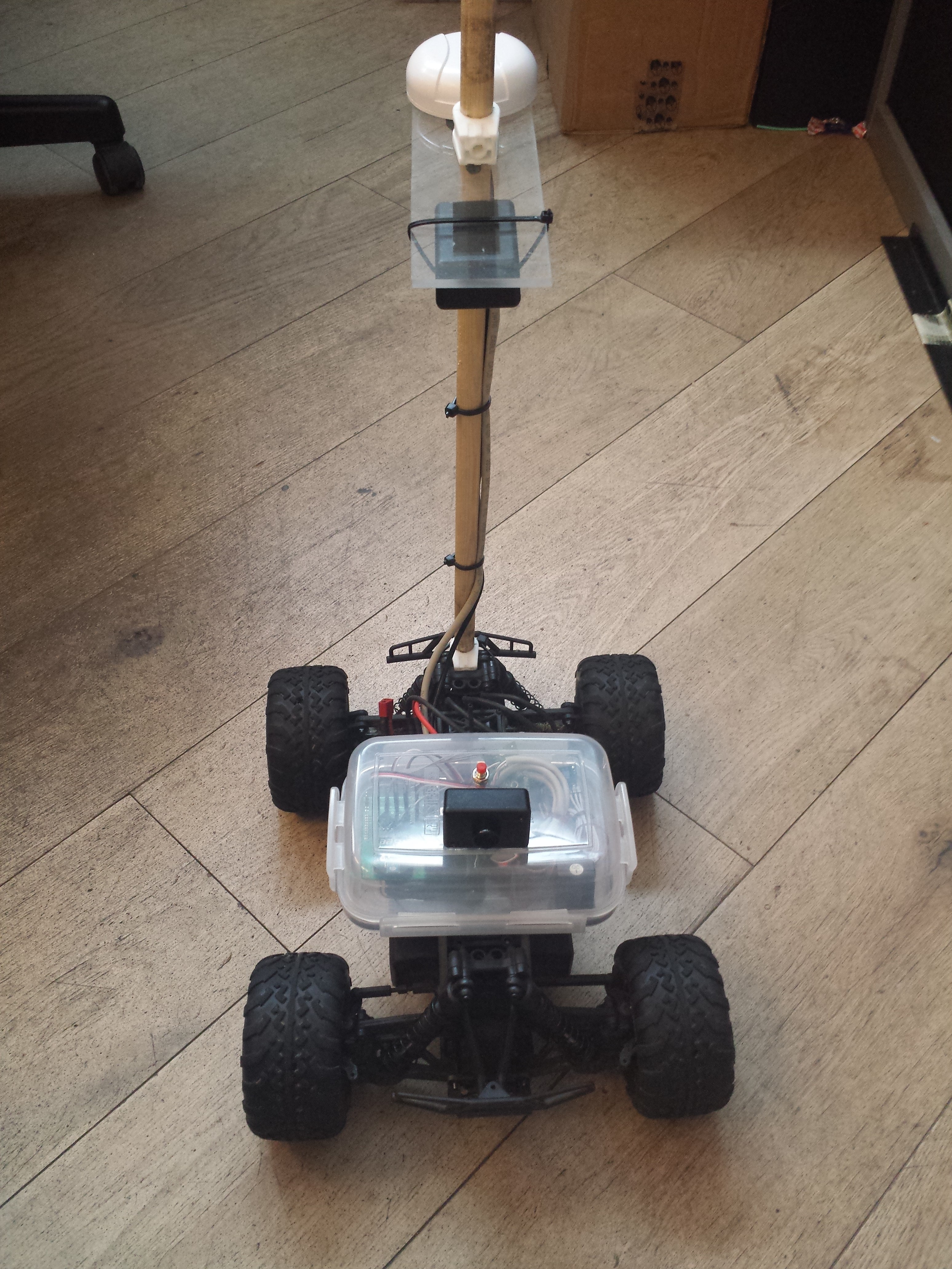
I stuck with the xBee but I moved the magnetometer away from the main board and chassis, to try and reduce the interference. I assumed the interference was magnetic flux coming from the huge brushless motor and large powerful steering servo in the car. If I mounted the magnetometer away from these, perhaps I’d get a more reliable reading. And so was born “broom-handle-bot”

SparkFun AVC 2013 autonomous robot

SparkFun AVC 2013 autonomous robot

While working on the prototype I was also researching better GPS solutions. The basic GPS module I was using only had an accuracy of about 2-5m. This would be tricky to avoid a barrel or hit a jump 1m wide. I had stumbled across SBAS while research GPS issues and this potentially could give me accuracy down to 1-2m. Much better. You can read the wiki page for more details, but effectively (IIUIC) the SBAS system sends a separate signal from a different set of satellites that contains data to improve the accuracy of the main GPS signal. It compensates for atmospheric interface, and other transmission errors. There are different SBAS systems in different parts of the world, WAAS in North America and GLONASS in Europe. I would need a GPS receiver that supported both. Again, with some googling, I found NaviLock and the NL-622MP MD6 GPS Receiver. The data sheet confirmed it supported WAAS and GLONASS, it uses the latest u-Blox chipset, and came in a handy mountable self-contained puck. I ordered one and it arrived. The only downside was the output was RS232 (+/- 15v) not TTL, so I’d need a level shifter board to connect it to the mBed. If I had spent more time looking, they do do a TTL version, which would have been easier …

The very first test of the new GPS puck was transformational. The old GPS wouldn’t get a lock inside my house, which made testing a real pain. I would have to write the code, upload it, then disconnect the system, walk outside in to the garden, test it in the cold, then come back in and debug it, then repeat. This wouldn’t have been so bad, if this was on a Sunday afternoon, but due to my job and family commitments, nearly all my tinkering was done at night, between the hours of 10pm and 2am. It was also the back end of winter, and still snowy some weekend. Testing in the garden at midnight in the snow wasn’t fun.
The new GPS got a lock inside. Plus it got a lock really quickly, within seconds. The old GPS took minutes. It was clear from the first few outside tests that the accuracy was much better and the reading more stable. The GPS used the uBlox 6 chipset, with came with a very detailed and advance desktop config and debug utility.

The basic system was working. However I still had magnetometer issues. The reading would vary wildly if the magnetometer was close to the car. Even if it was some distance way, it wasn’t reliable. It would point north, then I would rotate it 180 and it wouldn’t point S, it would read 160 degrees, then I point it north again and it would read -30. If I rotated it 360 degrees sometimes it didn’t move, sometimes it rotated 250 degrees. I tried lots of different configurations. Even on the bench with no magnets or metal close it wasn’t reliable.
After some extensive Googling, it seemed I need to perform a calibration. This would calibrate out basic interference if the interference was constant, like a steel mounting screw that was always in the same relative position to the sensor. This link explains the process. You take lots of readings from every orientation, imaging mounting the sensor on gimbals and spinning it on all axis, so the tip of the sensor scribes the outline of a sphere. Ideally you want a data cloud of points in all orientations from all three sensors; x, y & z.
Once you have the data set you need to do three things;

  1. You need to remove “erroneous” readings, called outliners. There are clearly (statistically) incorrect. These are obvious to spot manually as the sit outside the circle/sphere of normal readings.
  2. You need to normalise the data in all three axis, so all the maximum readings from all the of the x, y & z sensors have the same magnitude
  3. You need to shift the data so to each set of readings is centred on zero.

Imagine a point cloud that is slightly oval shaped. The normalisation process shifts and scales the cloud so it’s a perfect circle, orgined around zero.These scaling and offset numbers are then used to scale the raw reading to give better accuracy.

Compass Calibration - Before

Compass Calibration – Before

Compass Calibration - After

Compass Calibration – After

This worked to an extent, and the magnetometer was noticeably more accurate and stable, but I still had problems. So I thought I’d tried a different approach. I had an IMU sensor from a previous project. This sensor has 9 DoF (gyro, accelerometer & magnetometer) plus a CPU and contains a kalman filter to process the data. It will give Euler angles, and all I was after was “yaw” – Phi. The issue was the device was not I2C, but serial or SPI. The serial interface had complex packet structure and I didn’t have time to write and debug a parser, so I opted for SPI. I modified the code to read SPI and got a basic Phi reading from the device.
This was more accurate. But it now had a different problem. The issue with yaw calculating with a 9 DoF board, is the yaw cannot use the accelerometer data, as it rotates around the accelerometer axis so it never changes. It can only merge the magnetometer and gyro data. And this is susceptible to gyro drift. This manifested itself in the yaw reading slowing rotating even when the unit was stationary. There was a function in the devices to zero the gyros when the unit was at a known stationary position, but after time the drift returned. That clearly wasn’t going to work.

The final option was to try the same basic magnetometer code, but with these IMU magnetometer readings. You can read all the raw gyro, accelerometer, magnetometer readings, plus the processed (filtered) version, plus the Euler angles from the device.
It turned out the process (filtered) raw magnetometer readings were pretty stable. So I had my final solution. However … about a week before the competition!

Other posts in this series :
Scout sets new Autonomous Boat world record

Scout, an autonomous unmanned robot boat, has now traveled over 300 miles in 12 days in its quest to cross the Atlantic Ocean. Amazing. More details here http://gotransat.com/ and real time tracking here http://gotransat.com/tracking/.

Well done guys.

Whats the old saying … Measure twice, cut once ?

You know how I show images of me laying out components on colour print outs of my PCBs to check they fit ?

I broke my own rule and it bit me !

The OpAmp footprints on the PCB are TSSOP14 but the devices I bought are SOIC14 😦

AVC – Switching from Arduino to mBed

Once the initial Arduino prototype was built I started having problems with the board. I rigged it on the bench with two servos attached directly to the speed and steering outputs. The code kept crashing and the board would hang. Normally in strange ways. I would comment out lines of code, and it would be more stable, then I’d put different code in and it would crash again. It seemed to have little to do with the content of the code, and more to do with the *amount* of code…

I had this problem before with my balance bot. The code randomly crashed there too and if you run some basic compiler tools on the code, the code is very close to the RAM limit of the microcontroller.

I had been looking at mBed for a few months and had bought a board to play with and this seemed like a perfect project to learn mBed on. I could have switched to an Arduino Mega, which is what I did on my Balance Bot, but the Mega is physically so much larger, and I wanted to fit the resulting controller inside the RC car, so I bit the bullet and scrapped everything I’d done to date, and started again with mBed. There’s nothing better than a looming deadline and nothing currently working to focus the mind on learning a new platform. 🙂

I had an LPC1768 mBed which had much better specs. I would classify its advantages over Arduino as :

  • Faster – 100 MHz vs. 16 MHz. Six times more instructions per second means more power. I could read the GPS and magnetometer at a much faster frequency and baud giving me better accuracy and control.
  • More hardware serial ports – 1 UART on the Arduino vs. 3 UARTs on the mBed – I needed a fast serial port for the GPS and one for debugging via xBee.
  • Hardware I2C for the magnetometer.
  • More RAM (32 KB vs. 2KB on the Arduino) more than enough to run all the various libraries and calculations without crashing.
  • Hardware floating point – This is important for GPS as the LAT/LON coordinates are all floating point numbers. There would be lots of complex trigonometry with floating point numbers happening every second. Hardware floating point would be a huge improvement in performance.
  • The last benefit was unexpected. The mBed has an RTOS library that allows you to run multiple independent threads. This made the code design much simpler. Rather than having one big main loop, that has to do everything, I could split up the tasks in the threads. E.g. one just ingesting and parsing GPS NEMA data, one outputting debug information, one running the PID control loop, etc.

The design changed from Arduino to mBed over night and I planned a new board. Although this has only taken a couple of blog pages to explain, it took about 6 weeks in elapsed time. Lots of late night debugging, scratching my head, reading on the interweb and chatting to people on forums.

I designed another PCB for the mBed solution and using the cheap PCB fabs I calculated it would arrive a couple of weeks before the competition. I had no choice but to commit to this design. There would be no time to reinvent the solution a third time. In fact if it didn’t go well, I’d be soldering it on the plane, if I wasn’t lucky … 🙂

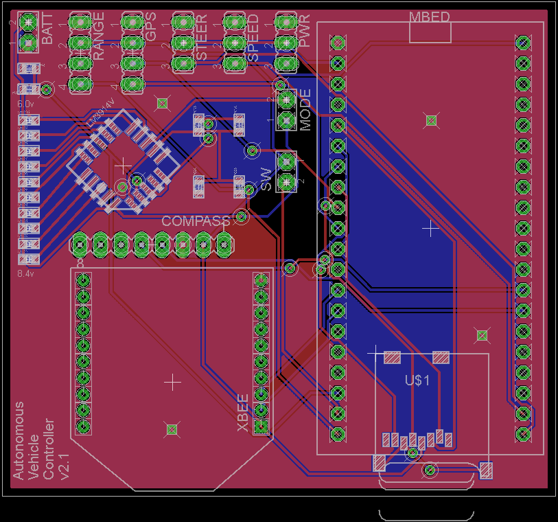
AVC 2013 mBed Custom PCB v2.1 layout

AVC 2013 mBed Custom PCB v2.1 layout

I added a battery meter to the final PCB design as a last minute addition. I had seen this video on the EEVblog describing the LM3914 LED driver. The worked example on the video was exactly what I needed to monitor the charge of my LiPo’s, so I added the circuit and LEDs to the final PCB. This would give me an easy visual reading of the battery condition before each run, reducing the risk of the run failing due to a low battery. In retrospect, I perhaps should have done this a different way. The LED driver was actually more complex and more expensive that driving the LEDs from the mBed directly. I have enough IO pins and I’m already taking an ADC reading of the battery voltage, but it seemed like a good idea at the time.

I sent the PCB design off which would give me a few weeks to convert the code.

I should point out here why I like having custom PCBs, instead of wire wrap or breadboards. I do jump to custom PCB very quickly in my prototyping phase. The simple answer is reliability. In the past I have run projects from a breadboard. But as always happens you drop the project, or it has to travel somewhere in a box, and suddenly two of the wires have popped out of the bread board. Typically you now waste hours tracing every connection to work out where they went and which ones have popped out. Plus with moving robots, the momentum of the bot tends to throw the boards around unless they are stuck down well, giving the same problem with wires coming lose. I like having a custom PCB. They are very cheap and easy to make (once you’ve used Eagle a few times) and they make the circuit an order of magnitude more reliable, much smaller and less messy. In addition they are just as easy to change if something is wrong, you can cut a trace and solder in a jumper wire in. Plus things like xBee, which has 2mm pitch legs, aren’t breadboard friendly, so you end up with breakout boards, again that come lose. Custom PCBs are just easy, cheap, and more reliable.

I started by porting the existing Arduino GPS and magnetometer libraries to mBed, which meant the bulk of my code would just migrate to the new platform. The mBed platform is fantastic. Its “proper” C++, not the cut down libraries of Arduino. I got things like printf back 🙂 which are huge resource hogs on Arduino.

There were other benefits too. There is a simple SD Card library, so I could store my waypoints on an SD card, which would mean making small edits during the competition wouldn’t mean I needed to recompile the code and upload it to the mBed, I could just edit the text file in an editor and re-read them.

I structured my code slightly differently to make use of the multithreading benefits of mBed too. I had three threads;

  • The first was dedicated to just ingesting the GPS NEMA strings and converting them in to numbers that were stored in a global variable structure. I ran the GPS at 4 Hz to give me good accuracy.
  • The second thread was dedicated to providing debug data. It ran every second, (or every 2 seconds) and dumped all the current readings of all the sensors and internal variables over the xBee. These would then be read by the desktop app and displayed in a user friendly way.
  • The final thread was the main loop. This ran the PID control and used the data from the GPS structure and magnetometer to feed the PID, and then set the steering servo with the output of the PID.

I got a prototype working on an mBed development board while I waited for the custom PCB to arrive. I used wire wrap as usual, with some jumper leads to plug in to the mBed. The prototype worked OK and I started to get a basic system working.

AVC 2013 mBed wire wrap prototype

AVC 2013 mBed wire wrap prototype


AVC 2013 mBed wire wrap prototype

AVC 2013 mBed wire wrap prototype

Here’s the test video the full system working on the bench for the first time. You can see the third channel switch the control between RC and mBed. During mBed control, the compass on the mBed controls the steering servo, and the wheels track the position of the compass. During RC control, the transmitter has control and the mBed does nothing.

Other posts in this series :

AVC – How difficult can it be ?

Ever since the SparkFun AVC started a few years ago, I’ve wanted to enter. But living in the UK made it difficult to justify the expense of flying to Colorado for a robot competition. This year, purely coincidentally I was in the US for a conference the week before the competition. The opportunity was there to enter so I decided to build a robot and enter the SparkFun AVC 2013.

The AVC on paper sounds simple 🙂 … Build an autonomous vehicle that can navigate an obstacle course without human intervention. The course is timed and you get bonus points for achieving certain tasks (going under a hoop, going over a ramp, etc.).

I decided to enter the ground competition, as the aerial challenge sounded way more complex. I’ve never built an aerial robot, so I thought I stick to something I had experience in. I decided to base my robot on a radio controller car chassis. I had an HPi Racing Savage Flux XS, which was perfect. It’s a 4×4 mini monster truck, that’s fast and simple. Just two controls, steering and speed. In addition, the radio it comes with has three channels, so I could use the 3rd channel as a control to switch between radio control and autonomous control, and quickly switch back to radio control during testing in the event it went berserk and headed for a tree.

My bot has a GPS receiver to provide its current position, and a magnetometer to provide its current heading. A microcontroller controls the speed and steering servos and a Radio Control switch can switch between autonomous control and manual control using the third channel. In addition the course has obstacles, so I need some basic obstacle avoidance. I used a small sonar to provide the distance to obstacles directly in front.

I needed a way to monitor and debug the car while it was hurtling round my garden during testing. I decide to add an xBee so I could get basic debug information from the car in real time, and (as I did with the balance bot) write a simple PC desktop app to display them in a user friendly way.

AVC 2013 High level system diagram

AVC 2013 High level system diagram

SparkFun provide the course details with all the GPS coordinates. The course is roughly rectangular with four sides, a start finish straight, a side with 4 barrels as obstacles, a side with a hoop to go under for bonus points and a side with a small ramp to jump, again for bonus points. The course is about 200 feet square, with the course being about 20 feet wide. With basic GPS accuracy of 2-4m this made the challenge perfectly achievable … easy huh !? If only …

AVC 2013 Ground Course ((c) Sparkfun)

AVC 2013 Ground Course ((c) Sparkfun)

Initial components

I started with components I already had. An EM-406A GPS module and a Pololu 3D magnetometer breakout board. I bought a MaxSonar sonar from CoolComponents and an RC switch from Pololu to give me a failsafe control.

The initial plan was to use an Arduino, as I have lots of them and lots of experience programming them. As mentioned before, I like old school wire wrap for prototyping, so I prototyped a basic Arduino shield to tie the 3 sensors together.

The initial testing went well. I used a third party GPS library and magnetometer library to ingest the data and I could get a basic heading to a GPS waypoint, and get a bearing from the magnetometer on the bench. The PWM output worked controlling two test servos, so confidently I sketched a custom PCB to shrink the design and make it more feasible to fit in the RC car, so I could start field testing in the garden.

AVC 2013 Arduino Custom PCB v1.0 board

AVC 2013 Arduino Custom PCB v1.0 board

AVC 2013 Arduino Custom PCB with components

AVC 2013 Arduino Custom PCB with components

Once the PCB arrived I had the basic software running. The premise of the control system is to navigate to waypoints, so the GPS coordinates as used to calculate a bearing from the current position to the next way point. This is the heading the car needs to steer. However, the car is on rough terrain and will never steer in a straight line. The course the car is taking is provided by the magnetometer, which gives the bearing the car is pointing. To reach the waypoint the difference between the car’s heading and the GPS bearing need to be kept as close to zero. One of the best ways of doing this is to use a PID controller.

I had a basic control loop written, for the Arduino, which looks something like this pseudo code:

While(CurrentWaypoint < TotalWaypoints) {
  MagneticHeading = GetMagnetometerHeading();
  GPSLocation = GetGPSLocation();
  GPSHeading = GetGPSHeadingToWayPoint(GPSLocation,WayPoint);
  PID_input = MagneticHeading – GPSHeading;
  ComputePID();
  SetSteering(PID_output);
  If (DistanceToWaypoint < 2m) then CurrentWaypoint++;
}

This should steer the car in a straight line from wherever it is, to a defined GPS waypoint. Once it gets within 2m of the way point, it moves on to the next waypoint. Once all the waypoints have been reached, it ends.

This is when the problems began…

Other posts in this series :
BalanceBot – Console App

Debugging Arduino programs can be difficult, as the only easy output method is a serial console. With lots of debug messages the console soon becomes full and difficult to read efficiently. The biggest issue is the console scrolls, so with lots of output the text scrolls past too fast to read. One solution is to write a simple app on your laptop/desktop that listens to the serial data and displays it in an app with a better layout. You can create individual text boxes that just display the values of key variables, and the app can scan the serial stream looking for these variables and update the text box every time it sees a new value.

Depending on your microcontroller code purpose, you can also chose more appropriate visual representations of your debug variables. For example, you could show an arrow on a compass to represent the value you get from a magnetometer, you can plot a point on a Google map page in and HTML control to show the position you get from a GPS, and you can display green and red dots to show the value of switches, etc.

I use Visual Basic, just because I find it easy. You can design the visual layout of the app easily, and the code is very simple, but *any* programming language will work. Pick one you are most familiar with. You don’t want to waste time building the debugging console, when you could spend that time debugging your microcontroller code.

I use two techniques in the serial protocol; I prefix each line with a symbol that defines what type of data the line contains and I use name / value pairs for data to display.

e.g.

#Init Motor Driver
#Init Wire library
#Init IMU
#Get first YPR
#Set initial Input variable
#Init IMU Setpoint
#Exit Setup
$StatusA = 1011
$CountA = 4294967255
$StatusB = 11101010
$CountB = 0
$Yaw = -130.54
$Pitch = -6.03
$Roll = 23.43
$Input = 23.4341
$Output = -400
$OutputA = -400
$OutputB = -400
$Heading = -137
$Button = 1

# – denotes debug messages. I add a time stamp to them and display them in a “messages” text box.

$ – denotes a name / value pair. The value is displayed in a text box for that name.

Instead of a difficult to read scrolling text window, I now have a stable windows app that displays each variable I want to track in an easy to read layout. In addition, I have a log of messages, with time stamps, I can scroll back through looking for interesting events. Finally, you can also decide to output some values are different frequencies, i.e. the fast changing values every 500ms, and the slow changing values every 5 seconds. The app also shows the current value for everything.

You can also get your microcontroller to listen to the input serial stream and use the app to send commands to your device. Add an XBee and now your microcontroller is wirelessly remotely monitored and controlled by your app on your desktop !

BalanceBot – Laser cut Acrylic

The frame of the robot is built from MicroRax but it has no “sides”. I needed to mount some switches, etc. plus I wanted to mount the Arduino board securely and the two mounting holes in the Arduino are at very specific locations which would be better secured to a flat surface. They didn’t line up with the MicroRax.

The initial prototype had a hardboard base, but I thought I’d use the opportunity to learn how to get laser cut plastic. I found a supplier, Ponoko, which had a very simple interface. A lot of laser cutting houses use AutoCAD or Illustrator file formats to define the shape to cut. As I didn’t have an applications that can produce these, I liked Ponoko, as it used PNG. This can be generated huge number of apps, a lot of which are free.

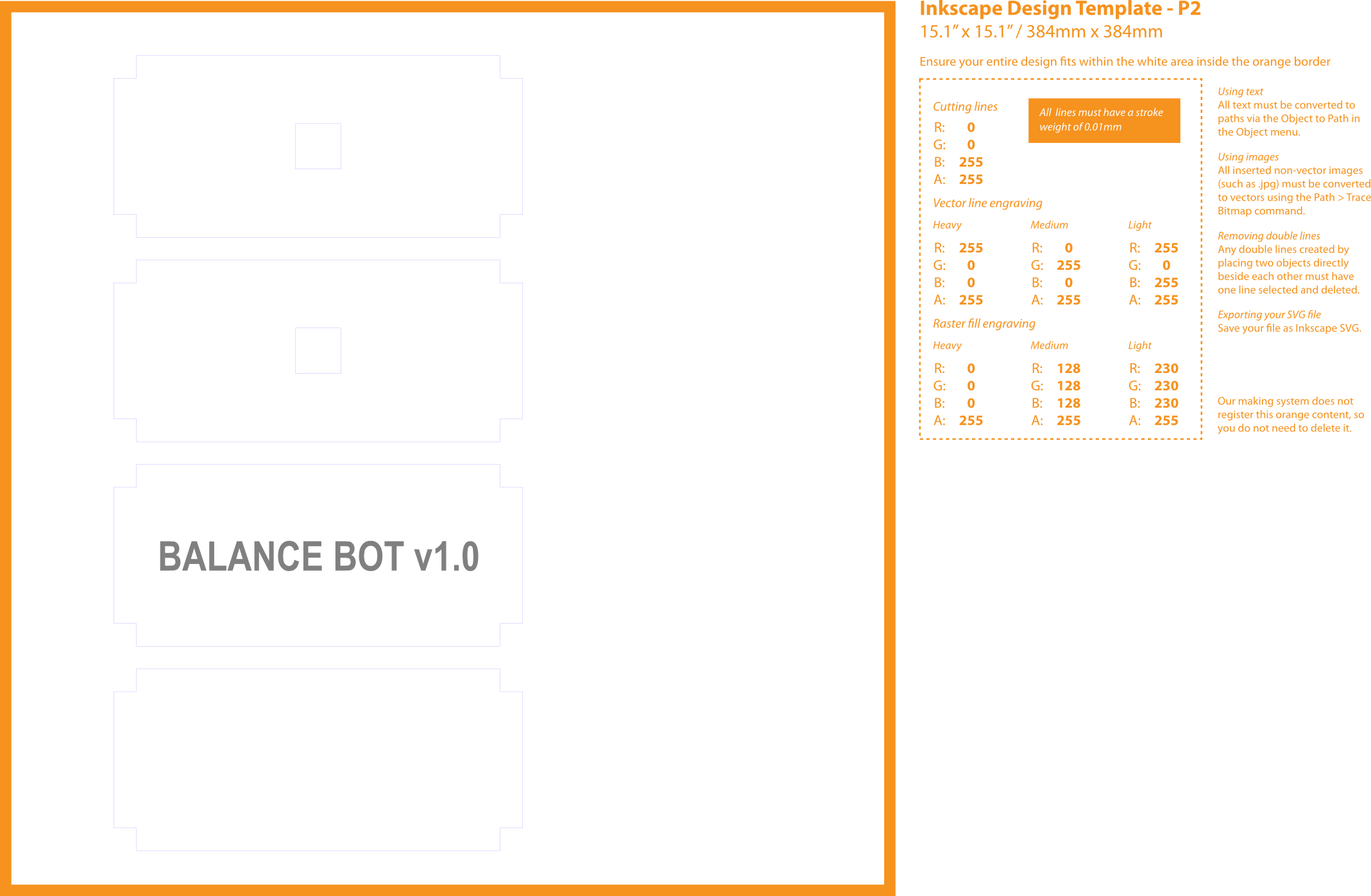
Ponoko provide a sample template. The format is very straight forward. The colour of the line in the file defines the cut the laser will make. E.g. Cut, engrave, etc. They also have a huge array of materials, including acrylic, leather, card, wood, paper, rubber, etc.

I designed a top and a bottom. The bottom has a hole for the cables. The top is engraved (no reason other than I wanted to try it and it looks cool :-)) I didn’t get the holes for the switches laser cut, I drilled them, as I didn’t know at the time what switches I would be using.

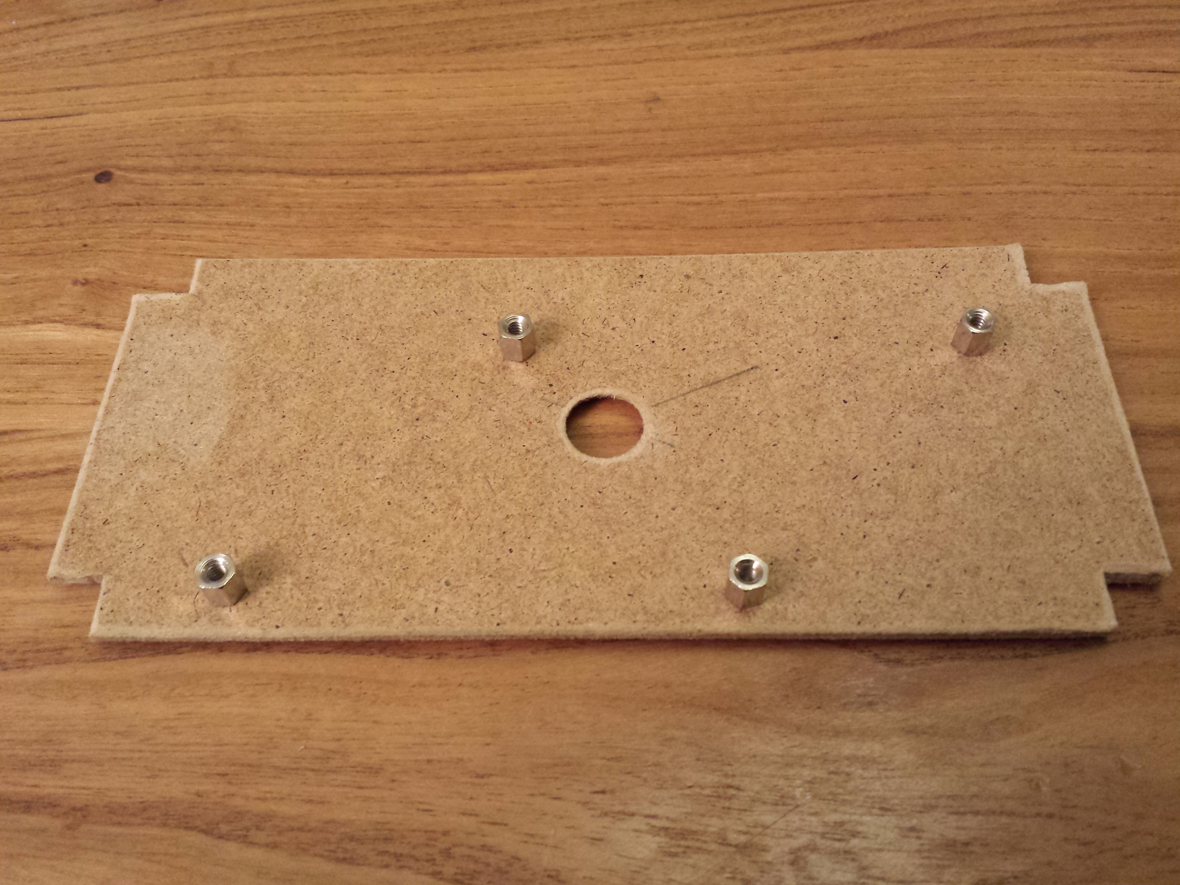
Hardboard BalanceBot floor with Arduino PCB mounts

Hardboard BalanceBot floor with Arduino PCB mounts

PNG file used to laser cut the acrylic. Different coloured lines represent different types of cut or engraving.

PNG file used to laser cut the acrylic. Different coloured lines represent different types of cut or engraving.

Laser Cut Acryilic sheets. Cut by Ponoko.

Laser Cut Acryilic sheets. Cut by Ponoko.

Laser cut acryilic top with laser engraving

Laser cut acryilic top with laser engraving

The acrylic panels made the robot look very professional, in fact people ask me where I bought it 🙂

The panels made mounting the boards and switches trivial. I used self-adhesive PCB supports for the Arduino. The holes on the Arduino are 3.2mm. I found PCB supports 6.4mm high from RS which fitted perfectly. The Acryilic is easy to drip, so I hand drilled holes for the switches and buttons.

AVC – It’s ready !

It’s ready ! My entry for the Autonomous Vehicle Competition in the US next week is built and (partially) tested. I’ve entered the Autonomous Vehicle Competition run by SparkFun Electronics, held in Boulder, Colorado. See : http://avc.sparkfun.com & http://www.sparkfun.com

Tupperware Bot !

Tupperware Bot !

I’ll do a series of more detailed posts after I come back, but here is a brief synopsis.

It’s an HPi Savage Flux XS radio controlled car underneath (The “world’s fastest mini monster truck”) It will do 55 MPH on a good day, but I won’t be running it anywhere near that fast. The brain is an mBed (ARM base microcontroller). Attached is a high accuracy GPS (I’m getting about 1.5-2m accuracy using SBAS), an electronic compass (So I know which way the car is pointing), an ultrasound range finder (to sense obstacles) and a big red “go” button ! 🙂

The mBed ingests the GPS data, range finder and compass data and works out where it’s currently pointing and the delta to where it needs to point to reach the next waypoint. The delta is fed in to a PID control algorithm that controls the steering servo. Currently the speed controller is a static speed (slow) but as I get more confidence in the testing, it will be proportional to the distance from the next waypoint (i.e. faster, then slowing as you near the turn point.) The range finder is processed and inserts an offset in to the PID control input if it detects an obstacle, to try and steer round it.

Other posts in this series :

BalanceBot – Arduino Code

With the use of the various libraries the main code loop is very simple. Once all the objects are initialised, the loop reads the robots angle, computes the PID output and uses that to set the motor speed and direction.

void loop()
{
my3IMU.getYawPitchRoll(ypr);
Input = ypr[IMU_ROLL];
myPID.Compute();
md.setSpeeds(Output,Output);
}

The system worked (ish). As mentioned previously, it took a while to find the PID parameters, and they are still not perfect. However I did get a problem.

The robot would balance, but after a few minutes, both motors would just turn on full. Sometimes one motor. The strange thing was sometimes the other motor would still be managed by the PID algorithm, and would change direction when the robot was tilted back and forth, so it wasn’t as if the Arduino had crashed. I initially thought there was a short circuit or lose connection but I couldn’t find one.

I had trouble in the past with other projects, where the code is large and complex, the Arduino sometimes exhibits strange behaviour. Not quite crashing, but being erroneous. I has a suspicion the device is running out of RAM. The programs either had too many variables, or too many recursive functions. I’ve not researched a way to model programs to estimate their RAM usage, or if there is a way to report RAM usage via the code. I’m sure there’s a way. Let me know if you have any ideas.

So, I just threw hardware at the issue, and upgraded the Arduino with a Mega, which has four times the RAM (8k on the Mega verses 2k on the Uno). This solved the problem immediately. Whereas the robot would “crash” every time on the Uno, the same code worked without any issue on the Mega.

One problem was the Mega though is it’s physically longer, so it sticks out of the side of the robot 😦

The other issue was the SPI and TWI pins on the Mega are on different pins to the Uno. Not a huge problem, but until I update the shield PCB, it means jumper wires.

Full code listing below:

#include <ADXL345.h>
#include <HMC58X3.h>
#include <ITG3200.h>
#include <Wire.h>
#include <EEPROM.h>
#include <FreeIMU.h>
#include <CommunicationUtils.h>
#include <DualVNH5019MotorShield.h>
#include <SPI.h>
#include <PID_v1.h>

//#define DEBUG
#include <DebugUtils.h>

// *** Duemilanova / Uno
// IMU uses I2C - pins A4 (SDA) & A5 (SCL)
// Quad counter uses SPI - pins D11 (MOSI), D12 (MISO) & D13 (SCK)

// *** Mega 2560
// IMU uses I2C - pins 20 (SDA) & 21 (SCL).
// Quad counter uses SPI - pins D50 (MISO), D51 (MOSI) & D52 (SCK)

// IMU constansts
#define IMU_YAW 0
#define IMU_PITCH 1
#define IMU_ROLL 2

#define Ku 20    // where is oscilates
#define Pu 0.4   // period of oscilation
#define Kp 0.6 * Ku
#define Ki (2 * Kp) / Pu
#define Kd (Kp * Pu) / 8

//IMU variables
float ypr[3]; // yaw/pitch/roll
FreeIMU my3IMU = FreeIMU();

//PID variables
double Setpoint, Input, Output;
PID myPID(&Input, &Output, &Setpoint, Kp, Ki, Kd, DIRECT); //or REVERSE

//MotorDriver
DualVNH5019MotorShield md;

void setup()
 {
  Serial.begin(115200);

  // Initialise Motor Driver:
  Serial.println("#Init Motor Driver");
  md.init();
  delay(50);

  // Initialise Wire Library:
  Serial.println("#Init Wire library");
  Wire.begin();
  delay(50);

  // Initialise SPI:
  Serial.println("#Init SPI library");
  SPI.begin();
  SPI.setDataMode(SPI_MODE0);
  SPI.setBitOrder(MSBFIRST);
  SPI.setClockDivider(SPI_CLOCK_DIV8);
  delay(50);

  // Initialise IMU:
  Serial.println("#Init IMU");
  my3IMU.init();
  delay(50);

  // Get Initial variables:
  Serial.println("#Get first YPR");
  my3IMU.getYawPitchRoll(ypr);

  // Initialise PID:
  Serial.println("#Set initial Input variable");
  Input = ypr[IMU_ROLL];
  Serial.println("#Init IMU Setpoint");
  Setpoint = 0;
  myPID.SetMode(AUTOMATIC);
  myPID.SetOutputLimits(-400,400);

  Serial.println("#Exit Setup");
}

void loop()
{
  my3IMU.getYawPitchRoll(ypr);
  Input = ypr[IMU_ROLL];
  myPID.Compute();
  md.setSpeeds(Output,Output);
  stopIfFault();
}

void stopIfFault()
{
  if (md.getM1Fault())
  {
    Serial.println("#M1 fault");
    while(1);
  }
  if (md.getM2Fault())
  {
    Serial.println("#M2 fault");
    while(1);
  }
}

BalanceBot – PID Controller

A  PID Controller is a software algorithm typically used to control industrial processes. A PID Controller (Proportional Integral Derivative Controller) calculates the difference between a measured variable and a desired set point. The controller attempts to minimize the error by adjusting the input.

A good example of why a PID Controller is better than other methods of control, is an electric oven. The input is the power to the heating element, the output is the temperature and the set point is the desired temperature.

Without a PID controller, If you turn the power on and off using a simple thermostat, when the temperature of the oven reaches the set point the oven will over shoot the temperature as there is residual heat left in the heating element. If you want the temperature of the oven to be 200 degrees, and have the element fully on until it reaches 200 degrees, then turn it fully off, the temperature will overshoot to maybe 205 degrees, then slowly cool until it reached 199 degrees when it will turn fully on again, however it will take time to heat up, in which time the oven has cooled to 195 degrees, and so it repeats. The oven will oscillate between 195 and 205 degrees, and not actually be a steady 200. This is fine for cooking sausages, but no good for a delicate chemical process.

The PID Controller has three values; the Proportional, the Integral and the Derivative values, denoted P, I, and D. Heuristically, these values can be interpreted in terms of time: P depends on the present error, I depends on the accumulation of past errors, and D is a prediction of future errors, based on current rate of change. By combining the three terms continuously the algorithm maintains the desired set point with minimal errors.

Simple huh ? Well kind of… The maths is a bit complex, but again, there are existing libraries that do it for you. On the Arduino site you can download a fully working PID Controller library, to integrate in to your project : http://playground.arduino.cc/Code/PIDLibrary

The only problem is you need to “tune” a PID Controller to your specific application. The P, I & D terms will be different for an oven, chemical tank, or balancing robot. There are lots of ways of tuning a PID Controller, from mathematical, to trial and error. A control systems friend of mine recommended I try the Ziegler–Nichols method.

The Ziegler–Nichols tuning method is as follows;

  • The P, I & D terms are referred to as “gains” Kp, Ki & Kd.
  • The Ki and Kd terms are first set to zero.
  • The Kp term is manually increased until the robot reaches the ultimate gain, Ku, at which point the it starts to oscillate.
  • The oscillation period Pu is measured and used to set the PID terms as follows :
  • Kp = 0.6 * Ku
  • Ki = (2 * Kp) / Pu
  • Kd = (Kp * Pu) / 8

This isn’t perfectly tuned to our specific system, but it’s a good approximation. PID tuning is a black art that requires a lot of knowledge and skill. This will do for the time being.

I am using the tilt angle of the robot as the input and the speed of the motors as the output.

The code is quite simple. The three variables are all floating point numbers.

double Setpoint, Input, Output;

The PID object is instantiated with the three PID values I calculated from my Ziegler–Nichols tuning method

PID myPID(&Input, &Output, &Setpoint, Kp, Ki, Kd, DIRECT);

The desired set point is 0 degrees, i.e. the robot is perfectly upright

Setpoint = 0;

Then in my main loop I get the angle of the robot, run the PID compute function, and using the output set the motor speeds.

void loop() {
  my3IMU.getYawPitchRoll(ypr);
  Input = ypr[IMU_ROLL];
  myPID.Compute();
  md.setSpeeds(Output, Output);
}

That’s the theory anyway … the results were mixed. It took a number of attempts to find the oscillation gain and period (Ku & Pu) accurately. And with those values, the PID controller wouldn’t balance the robot. It took lots of manually trial and error of various values to find something that was stable. PID tuning is very much a black art.

I did get it to balance though and it was more stable that the equivalent “cubed” algorithm I was using. However with the IMU code and the PID code on the Arduino, I started getting problems with the Arduino crashing. I can only assume it was running out of RAM.

I switched to an Arduino Mega and everything worked fine. So I’ve stuck with that for the time being. The Mega is much more stable, however the custom PCBs I made don’t fit the Mega, so the wiring is messy, plus the Mega sticks out of the frame. Next job is to make the PCB as a Mega Shield and turn the board round long ways so it fits better.

The PID controller is still not perfect, but it’s relatively stable. You can see it recovers from oscillation, which the basic controller didn’t. But It still drifts badly, and still falls over eventually. But progress none the less.I need to get the Quadrature decoders working so I can stop the drifting.

Here’s a short video of the PID Controlled BalanaceBot in action.